General
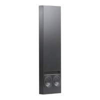
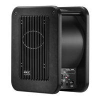
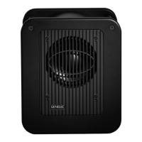
The Genelec 5041A Active In-Wall subwoofer
system consists of a subwoofer enclosure
and a matched RAM3 remote amplifier
module. It has been designed to the same
rigorous standards as Genelec’s high-per-
formance HT series active Home Theater
loudspeakers.
Unpacking
When unpacking, check that nothing is miss-
ing or damaged in transit. If there is a problem
with the product, contact your local Genelec
dealer. A Genelec 5041A system includes
the following items:
• 5041Aenclosureunit
• Grilleframeandgrilleinsert
• Fourmountingbrackets
• RAM3amplierunit
• M4x16 and M4x30 thumb screws
for the grille frame
• Plasticwashersforthethumbscrews
• Mainspowercable
• One 4-pole and one 2-pole cable
connector
• 12 4,2x32 screws for the mounting
brackets
Installation
We recommend that you use the services of
an authorized installation specialist for the
installation of the 5041A subwoofer.
Choosing the Location
for the Subwoofer
Usually the best place for the subwoofer is
slightly offset from the centerline of the wall.
Positioningthesubwoofernearacornerwill
boost the bass level at lower frequencies and
may cause asymmetrical spatial imaging.
When using multiple subwoofers connected
togetherusingtheLINKOUTconnectorson
theRAM3ampliers,thesubwooferenclo-
sures should be placed close to one another
toachieveefcientsummingofthesignal.
Subwoofer Cabling
A2-conductorcableneedstoberunbetween
theRAM3amplierandthesubwooferenclo-
sure. Two cable connectors are supplied with
the loudspeaker system, a four-pole connec-
tortottheconnectorontheamplieranda
two-poleconnectortottherespectiveinput
at the bottom of the subwoofer enclosure.
Useagoodquality2-conductorcableand
make the cable runs as short as possible.
See Table 1 for recommended cable gauges.
Theconnectorsacceptacableupto6mm
2
(9 gauge) thick.
Attach the cables to the connectors pro-
vided with the kit. Be sure to maintain cor-
rect polarity when connecting the cables. The
correct pin sequences are marked on the
amplierandsubwooferconnectors.Start-
ingfromthetop,thersttwopolesonthe
4-poleamplierconnectorare+and-forthe
subwoofer and 3 and 4 provide connection
toa12Vtriggerremotecontrol.Securethe
cabletothestrainrelieftienexttotheloud-
speaker connector.
Rout the cables away from electric, video
or phone cables, which might induce hum
into the system.
Installing the Subwoofer
Enclosure
The Genelec 5041A subwoofer enclosure
is designed for floating installation using
the provided mounting brackets that pre-
vent unwanted vibration transfer from the
subwoofer to the wall structure. The enclo-
sure is held in place by rubber springs, clear
ofanyxedpartofthewall.
The woofer protection cover should be
left in place until the drywall is installed. It
provides a cut-out template for the drywall
installers and protects the bass drivers during
all stages of work.
Before the installation, make sure that
there is sufcient space for the subwoofer
in the chosen location. The minimum dimen-
sions are:
1.Freedepthbetweenthesheetrock(=width
of the wall studs) 89 mm (3
1
/2")
2.Freeverticalspace1308mm(51
1
/2")
3.Freehorizontalspacebetweenthe wall
studs360to440mm(14
3
/16" to 17
3
/8")
Firstattachthetwolowerbrackets.Note
that the lower edge of the cut-out will be
140 mm (5
1
/2") above the lowest edge of the
bracket.
The flanges on the bracket correspond to
the minimum permissible mounting depth.
Attach the brackets to the studs so that the
edge of the flange is level with the inside
edge of the stud. This will automatically pro-
videsufcientclearanceforthesubwoofer.
Nextconnectthesubwoofercabletothe
connector at the bottom of the subwoofer
enclosure and position the enclosure on the
lower brackets. The rubber springs on the
brackettthegroovesonthebottomofthe
enclosure.
Secure the subwoofer in place by attach-
ing the top brackets to the studs. Align them
in the same way as the lower brackets and
ensure that the rubber springs press against
the bottom of the grooves, holding the
subwooferrmlyinposition.
Check the positioning of the enclosure
by placing a level on the studs at different
heights. Check also that the enclosure is not
touching any other part of the wall structure.
As the enclosure may vibrate when played
at high output levels, a clearance of at
least 3 mm (1/8") is required between the
subwoofer enclosure and drywall or any
other solid part of the wall. Slight adjust-
ments can be made by carefully bending
the brackets.
Installing the drywall
The protective cover on the bass drivers pro-
vides a template for the cut-out. Measure its
location and cut an opening in the sheetrock
accordingly.
Installing the Grille
Once the drywallis installed, remove the
bass driver protective cover by unscrewing
thethreePhillipsscrewsholdingitinplace.
Attach the grille frame with three thumb
screws.NEVERusethePhillipsscrews!Do
not tighten the thumb screws more than is
needed to hold the frame in place. Be care-
Cable gauge Max.length
2,0mm
2
(14 AWG) 30 m (100 ft)
3,3 mm
2
(12AWG) 40 m (130 ft)
5,3 mm
2
(10 AWG) 60m(200ft)
Table 1. Recommended cable thicknesses for
different lengths of cable
Genelec 5041A Active In-Wall Subwoofer
 Loading...