Do you have a question about the Generac Power Systems 004721-0, 004722-0, 004723-0, 004724-0, 004725-0, 004725-1, 004725-2, 004725-3, 004726-0 and is the answer not in the manual?
| Brand | Generac Power Systems |
|---|---|
| Model | 004721-0, 004722-0, 004723-0, 004724-0, 004725-0, 004725-1, 004725-2, 004725-3, 004726-0 |
| Category | Inverter |
| Language | English |
Emphasizes the importance of reading and understanding the manual for safe operation.
Covers general safety precautions and warnings applicable to the generator.
Details specific dangers and precautions related to electrical shock and voltage.
Outlines safety measures to prevent fires associated with the generator.
Provides warnings and precautions regarding potential explosions.
Outlines operator responsibilities for safe operation and maintenance.
Guides users on how to find authorized service dealers for assistance.
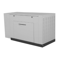
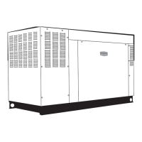
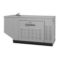
Describes the generator's function, ratings, and model numbers.
Details the necessity and guidelines for installing a transfer switch.
Explains the sequence of events for automatic generator start and operation.
Describes the single-phase, three-wire AC output configuration.
Identifies the main circuit breaker included with the unit.
Discusses the factory fuel system and options for propane conversion.
Explains safety switches that automatically shut down the engine.
Provides instructions for safe unpacking and initial inspection of the generator.
Offers safety warnings and guidelines for lifting the generator.
Lists detailed technical specifications for the generator and engine.
Provides data on fuel usage for different models and fuel types.
Guides on converting the fuel system from natural gas to propane.
Lists specific torque values for engine component assembly.
Advises on the correct type and viscosity of engine oil for various temperatures.
Provides guidance on coolant mixture and type for the cooling system.
Lists essential checks and considerations before starting the installation process.
Details the critical steps and safety requirements for installing the standby generator.
Provides guidelines for selecting an optimal and safe installation site for the generator.
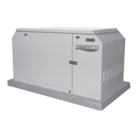
Describes the requirements for securely mounting the generator.
Illustrates a typical standby electric system setup with a transfer switch.
Explains a method to manage critical loads within generator capacity.
Describes a method for powering all loads, with potential for generator overload.
Details the importance and procedure for properly grounding the generator.
Discusses the generator's ungrounded AC neutral and grounding recommendations.
Explains how to connect the start signal wires for automatic transfer switch operation.
Provides detailed instructions and safety warnings for installing the generator battery.
Outlines essential steps to prepare the generator for its initial start-up.
Reinforces transfer switch installation requirements and compliance.
Covers checks for the fuel supply system before operating the generator.
Details checks for engine oil level and recommendations.
Explains checks for the engine cooling system and coolant.
Describes how to check and adjust engine fan belt tension.
Covers pre-operation checks for the electrical system and battery.
Explains the operation of the generator with a Generac GTS transfer switch.
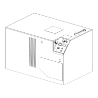
Identifies and describes the various components on the generator's control console.
Details the procedure for manually transferring loads and starting the engine.
Guides on setting up the system for fully automatic operation.
Explains the process for setting and performing the weekly generator exercise cycle.
Describes the function and connection of the engine block heater.
Lists maintenance tasks recommended for authorized service facilities at various intervals.
Discusses maintaining unobstructed airflow and exhaust system safety.
Explains the DC electrical system's overload protection mechanisms.
Details procedures for checking engine oil, battery fluid, and coolant levels.
Lists routine maintenance tasks that owners can perform.
Describes monthly inspection of cooling system hoses and clamps.
Outlines a monthly visual inspection for damage and leaks.
Details quarterly inspection of the exhaust system components.
Describes inspection and tension check of fan belts.
Advises on visual inspection of the electronic governor and cautions against adjustment.
Provides step-by-step instructions for changing engine oil and oil filter.
Guides on how to replace the engine air cleaner element.
Details procedures for checking, cleaning, gapping, or replacing spark plugs.
Recommends annual coolant draining, flushing, and refilling by a service facility.
Covers general maintenance tasks like cleaning and battery handling.
Outlines procedures for inspecting battery posts, cables, and fluid levels.
Specifies the correct battery type and number for replacement.
Presents a comprehensive schedule for recurring maintenance tasks based on time or hours.
A table listing common problems, their causes, and recommended corrections.
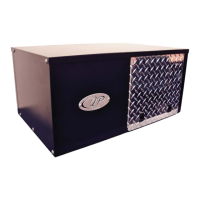
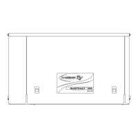
Visual representation of the generator's physical layout and connections.
Contains wiring diagrams and electrical schematics for the generator system.
Detailed wiring diagram for the generator's control panel assembly.
Wiring diagram specific to the 1.5L engine used in the generator.
Provides a schematic representation of the generator's electrical system.
Exploded view and parts list for the generator's governor assembly.
Exploded view and parts list for the generator's mounting base.
Exploded view and parts list for the generator's standard compartment.
Exploded view and parts list for the generator's acoustic compartment.
Exploded view and parts list for the generator's control panel.
Exploded view and parts list for the generator's engine components.
Exploded view and parts list for the generator's radiator assembly.
Exploded view and parts list for the generator's fuel system components.
Exploded view and parts list for the generator's alternator assembly.
Explains warranty rights and obligations specific to California emissions standards.
Details the warranty coverage for emission-related components.
Outlines the owner's responsibilities regarding maintenance and warranty claims.
Provides general terms and applicability of the emission control system warranty.
Details the standard two-year limited warranty for Guardian prepackaged generators.
Outlines the warranty coverage for labor and parts over the specified period.
Lists exclusions and conditions that void the warranty.
Lists specific components considered emission-related parts under warranty.
States limitations on Generac's liability for damages.