PART 2
AC GENERATORS
Page 50
Section 2.4
Diagnostic Tests
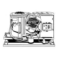
PIN 5
PIN 14
J5 CONNECTOR
HARNESS SIDE
63 VAC
5
9 8 7 6
4 3 2 1
1014 13 12 11
Figure 49. 10-20kW Fixed Excitation Test
Procedure: Rotor Amp Draw
1. Disengage the MIN/MAX feature and manual scale on the VOM.
2. Set VOM to measure DC amperage.
Note: Consult the meters documentation for proper setup
procedure. See Section 1.4 “Measuring Current” for fur-
ther information.
3. Connect the black (negative) meter test lead to Pin 13-J5
and the red (positive) test lead to the positive battery
terminal. See Figure 50.
4. Measure and record the static rotor amp draw.
5. Set AUTO-OFF-MANUAL switch to the MANUAL position.
6. Measure and record the running rotor amp draw.
7. Acknowledge and reset the “under-voltage” present on the
controller; leave AUTO-OFF-MANUAL switch in the OFF
position.
Results
1. Using the values recorded in the above procedure,
compare the results to Table 10 “Results – Fixed
Excitation Test/Rotor Amp Draw Test”. Determine the
appropriate lettered column to use and refer back to the
flow chart. The rotor amp draws area calculated amp
draw and actual amperage readings may vary depending
on the resistance of the rotor.
Note: To calculate rotor amp draw take the battery voltage
applied, divided by the actual resistance reading of the
rotor. Rotor resistance can be measured between Pin 13
J5 and Pin 12 J5.
12.9VDC
12.3 Ohms x 1.05 DC Amps
Example
Model 17kW
Wires 2 and 6 Voltage 53 VAC
Wires 11 and 22 Voltage 31 VAC
Static Rotor Amp Draw 1.09 Amp
Running Rotor Amp Draw 1.10 Amp
These results match Column B in the chart. Refer back to
Problem 1 and follow letter “B”
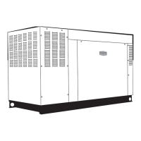
Figure 50.
5
9 8 7 6
4 3 2 1
1014 13 12 11
PIN 13
J5 PIN 12
J5 PIN 13
RED
J5 CONNECTOR
HARNESS SIDE
POSITIVE BATTERY
TERMINAL
1.09 DC
Amps
FIELD BOOST DIODE
OHM’S LAW
ROTOR
11.83Ω
11.83Ω
12.9 VDC
12.9 VDC
4
56
0
VOM METER
1.09 DC
Amps
1.09 A
BATTERY
+ -
Figure 51. Rotor Amp Draw Test
 Loading...