6 Owner’s Manual for Portable Generator
Connection Plugs
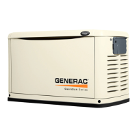
120 VAC, Duplex Receptacle
The 120 Volt outlet is overload protected by
the 20 Amp push button circuit protector. See
Figure 2-3.
Figure 2-3. 120 VAC, Duplex Receptacle
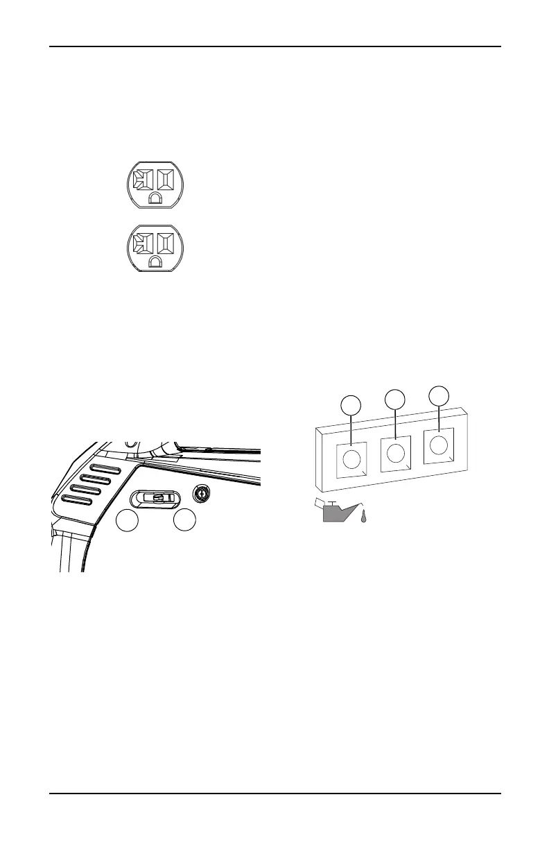
Run/Choke Switch
This controls the choke operation. See Figure
2-4.
• The RUN position (1) is for normal opera-
tion and to gradually reduce the use of the
choke.
• The CHOKE position (2) switches the fuel
valve on to start the engine.
NOTE: The CHOKE is not required to start a
warm engine.
Figure 2-4. Switch (example)
USB Outlets
The 5 VDC, 1/2.1 Amp USB outlet allows
charging of compatible electronic devices.
See Figure 2-2 for location of the UBS outlets.
Economy Switch
The economy switch has 2 modes of opera-
tion:
• On: The quietest mode and best when run-
ning appliances or equipment that are
resistive loads (non-motor starting), (exam-
ple: TV, video game, light, radio).
• Off: Best when running a both inductive
(motor-starting) and resistive (non-motor
starting) loads, especially when these loads
are turning on and off (example: RV, air
conditioner, hairdryer).
See Figure 2-2 for location of the economy
switch.
Generator Status Lights
See Figure 2-5.
• Overload LED (red): Indicates system
overload (2). During motor starting it is nor-
mal for the overload LED to illuminate for a
few seconds. If LED stays illuminated and
the ready LED turns off, the engine will con-
tinue to run without output power. Remove
all applied loads and determine if attached
devices exceed recommended output
power. Check for faulty or shorted connec-
tions. To restore electrical output, turn dial
OFF to reset. Start engine. If condition was
corrected, the orange LED will not illumi-
nate and electrical output will be restored.
Loads can be applied once the green LED
illuminates. If the orange LED returns, con-
tact an IASD.
• Low Oil Level LED (yellow): Illuminates
when oil level is below safe operating level.
Engine shuts down (1).
• Power LED (green): Indicates output from
generator (3) (unless there is a low oil or
overload condition).
Figure 2-5. Status Indicators
Circuit Protectors
The AC receptacles are protected by an AC
circuit protector. If the generator is overloaded
or an external short circuit occurs, the circuit
protector will trip. If this occurs, disconnect all
electrical loads to determine the cause of the
problem before using the generator again.
Reduce the load if the circuit protector is
tripped.
NOTE: Continuous tripping of the circuit pro-
tector may cause damage to generator or
equipment.
Push the button of the protector to reset the
circuit protector.

 Loading...