3-4
SECTION 3: CARBURETION AND FUEL SYSTEM
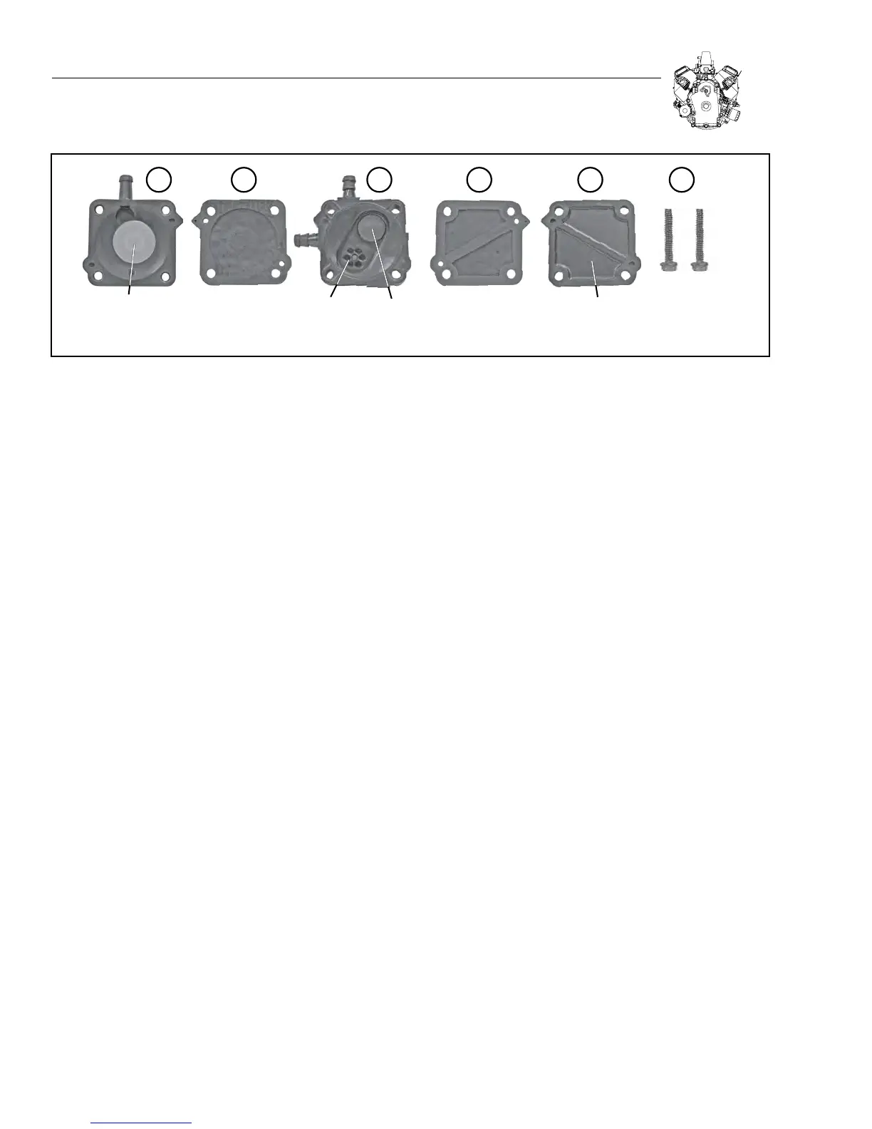
Fuel Pump Breakdown (see Figure 3-10):
1. Lower Spring Assembly
2. Lower Diaphragm
3. Check Valve Assembly
4. Upper Diagram
5. Upper Vent Assembly
6. Mounting Hardware x 2
As crankcase vacuum is built up the Lower Diaphragm pulls down
against the Spring Return and allows fuel to flow through Check-Valve
2. As pressure builds up in the crankcase, the Spring Return pushes
up against the Lower diaphragm, allowing fuel will flow through Check-
Valve 1 and out the fuel port.
LP (LIQUID) - FUEL SYSTEM
*
Proper service and repair is important to the safe and reli-
able operation of all gaseous fueled engines. Any servicing
or testing of a gaseous fueled engine must only be performed
by qualified personnel. Always follow applicable installation
and service procedures. An example of these requirements
is found in NFPA-58 for liquid propane. These are US Federal
standards. Worldwide standards vary. Local, city, and state
requirements may also have certain requirements that must
be observed.
LP (Liquefied Petroleum Gas) is a gaseous fuel and when stored under
pressure, becomes a liquid. Although a vapor forms at the top of the
tank, this particular system uses a liquid withdrawal method, drawing
liquid from the bottom of the tank.
This is accomplished with a special valve that is installed on a normal
propane cylinder with a tube that is attached to the valve and extends
to the bottom of the storage tank. Pressure in the tank forces liquid
propane through the tube when the valve is opened.
The Generac LP system starts with a pressure relief valve to prevent
excessive pressure from building in the system during shutdown.
This is followed by a 12 volt (normally closed) electric solenoid,
which prevents the flow of fuel when the ignition key is off. When the
ignition key is turned on, the solenoid opens and allows liquid LP to
flow to the regulator.
The liquid fuel vaporizer/regulator converts liquid propane to vapor.
The vaporizer/regulator uses either spent engine cooling or engine oil to
provide heat to aid in the evaporation process. The vaporizer/regulator
controls the vapor supply to an amount required by the engine. The
engine’s intake vacuum draws LP into the fuel mixer on an on-demand
need. When the engine is off, LP no longer flows from the vaporizer/
regulator to the engine (see Figure 3-32).
TROUBLE SHOOTING
*
CAUTION! Gaseous fuels are highly explosive; do not use flame
or heat to test the fuel system for leaks. LP gas is heavier than
air and tends to settle in low areas; even the slightest spark
can ignite these gases and cause an explosion.
Note: Don’t assume that the fuel system is the problem. Verify that
the engine has spark and enough compression to start the engine
before proceeding with the following steps.
SPRING
RETURN
1 2 3 4 5 6
LOWER
DIAPHRAGM
UPPER
DIAPHRAGM
VENT: UPPER
VENT ASSEMBLY
FUEL
CHECK-
VALVE 1
FUEL
CHECK-
VALVE 2
HARDWARE
Figure 3-10. Fuel Pump Assembly