Figure 3-19. Rotate The Diaphragm To Align the
Cover Screw Holes
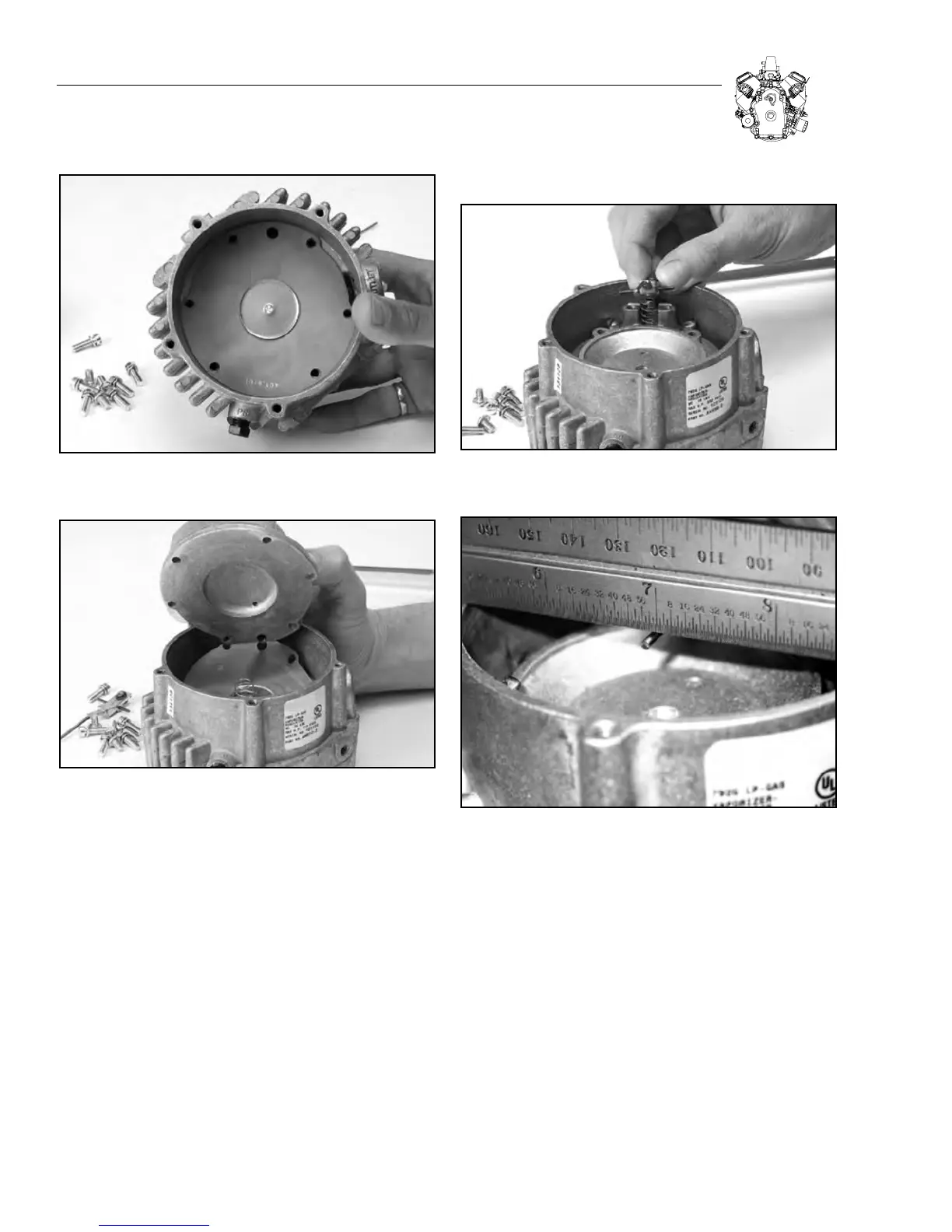
Figure 3-20. Install Primary Spring, Primary Cover and Screws
9. Place secondary valve spring (5/16” dia. x 5/8’ long) in spring
recess near secondary orifice. Replace secondary lever, pivot
pin, 1.19” long, and two screws, 10-32 x 0.310”. Make sure the
spring fits over the spring boss on the secondary lever. Tighten
screws evenly to 30 in. lbs. ±3 in. lbs. (3.39 Nm ± 0.339 Nm).
See Figure 3-21.
10. The secondary lever (except for the bent tail tip) should be level
or flush with the top of casting. Bend tail end of lever if necessary
but do not use excessive force on the rubber valve against the
orifice. See Figure 3-22.
11. The secondary lever has a soft valve surface on an aluminum
insert which must be swiveled into flat contact with the orifice.
Place a pointed instrument in the top indentation of the valve. Apply
slight downward pressure and with a gentle rotary motion, swivel
the valve into flat contact with the orifice. These valve inserts are
not sold separately but are crimped at the factory with proper
tension to allow movement but still hold their position. See Figure
3-23.
Figure 3-21. Install Secondary Valve Spring,
Lever and Pivot Pin
Figure 3-22. Make Sure Secondary Lever is Flush
With Top of Casting
12. Attach primary pressure gauge at the primary pressure test port
opening. See Figure 3-24.
13. Attach air pressure hose to the regulator fuel inlet with
approximately 100 psi, ±10 psi air pressure. See Figure
3-25.
14. Slowly depress the secondary lever bent tail end until you are
able to detect flow out of the secondary orifice. Let the lever then
slowly return to the closed position. Observe the primary pressure
reading on the installed gauge. It should be between 0.8 and 2.5
psi. If it is not, recheck your work in the primary fuel section. See
Figure 3-26.
3-8
SECTION 3: CARBURETION AND FUEL SYSTEM