3-9
SECTION 3: CARBURETION AND FUEL SYSTEM
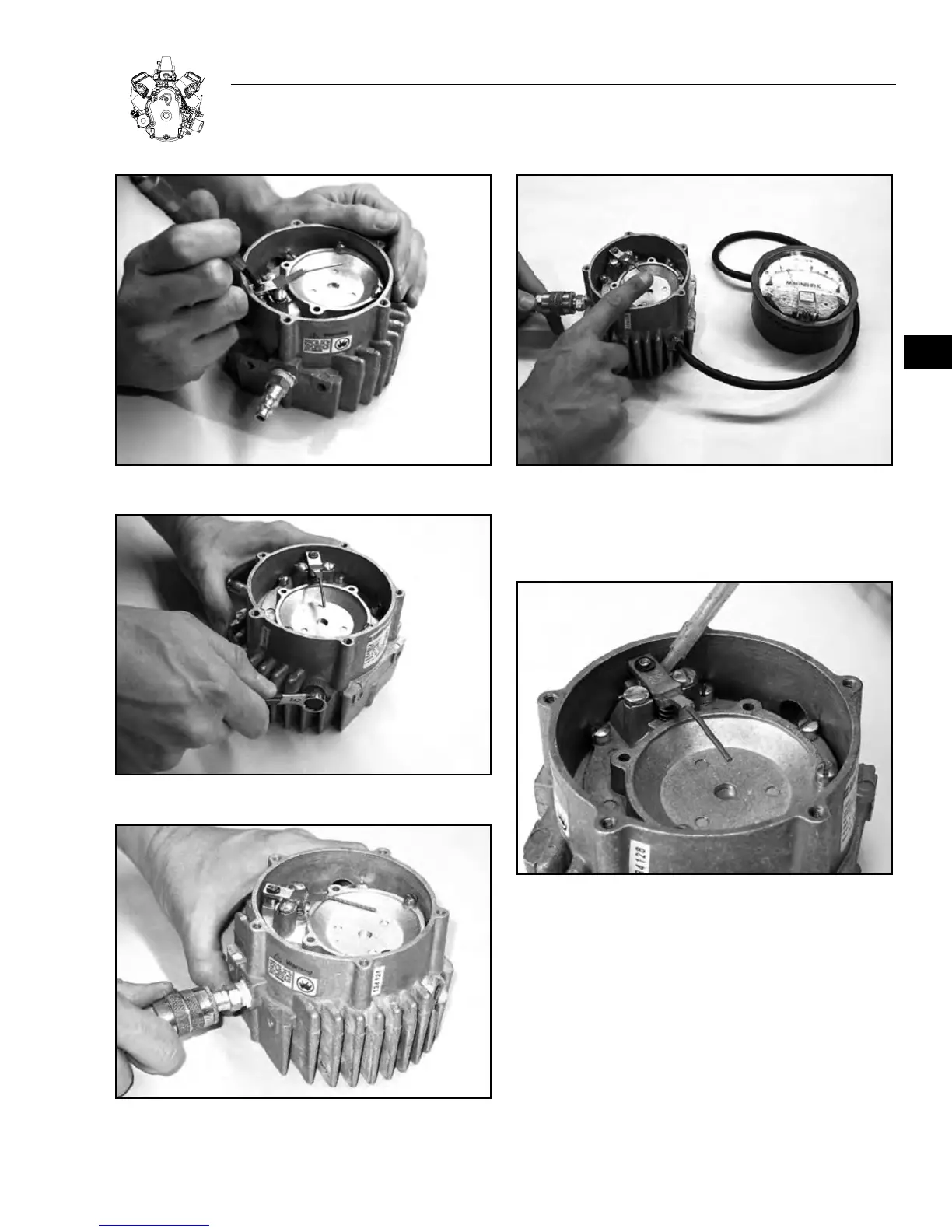
Figure 3-23. Positioning Secondary Lever Valve
Figure 3-24. Primary Pressure Test Port Opening
Figure 3-25. Attach Air Pressure Hose
Figure 3-26. Check Primary Pressure Reading
15. Check around the secondary seat for leaks using a liquid
leak detector solution. If a leak is detected, repeat Step 11
to insure no leakage at the secondary seat. See Figure 3-27.
Figure 3-27. Check Secondary Seat for Leaks
16. Turn off the air supply. Install the secondary diaphragm by
hooking the secondary lever through the center pin. If the screw
hole tabs do not line up with the casting, remove and rotate
the diaphragm 180 degrees and reinstall. See Figure 3-28.
17. Install secondary cover and align the cover and diaphragm
notches. Carefully start all five screws, 20-32 x 0.630”, through
cover and diaphragm holes. Tighten evenly, in a criss-cross pat-
tern, to 30 in. lbs. ±3 in. lbs. (3.39 Nm ± 0.339 Nm). See Figure
3-29.
3