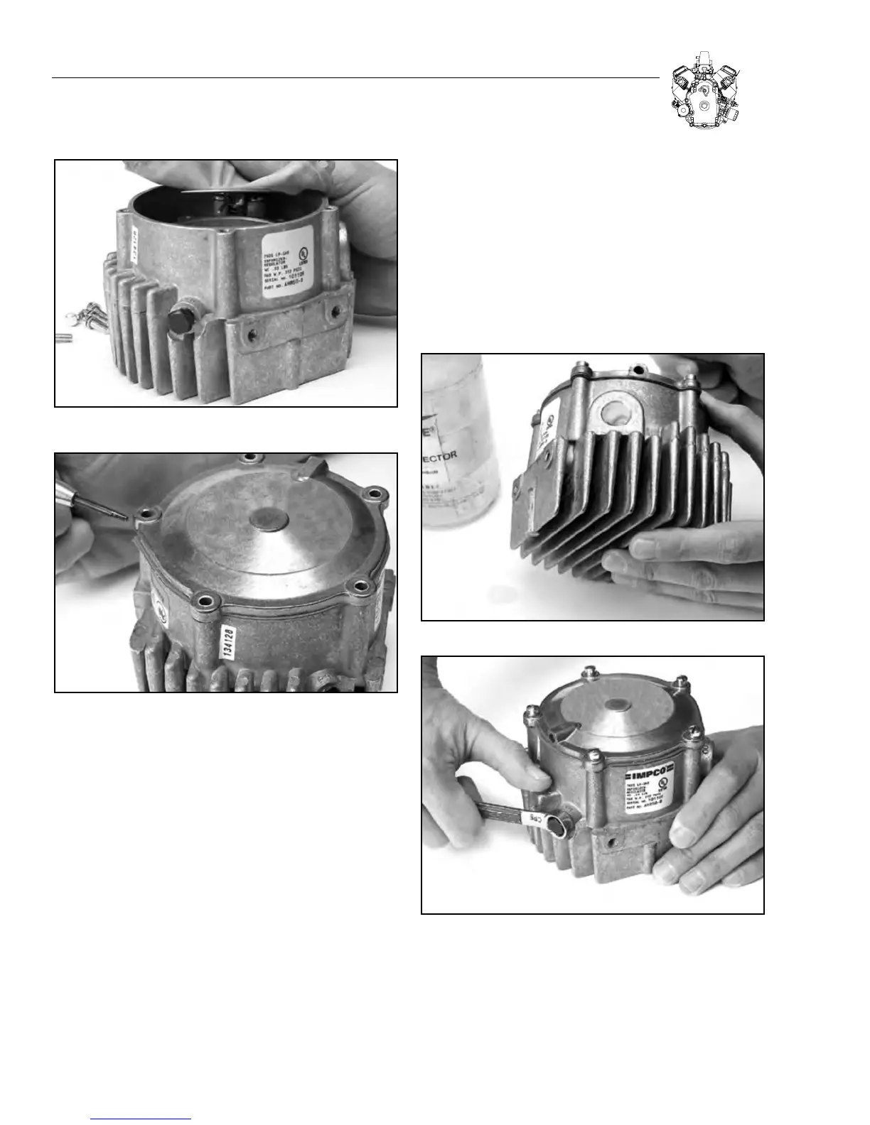
Figure 3-28. Install Secondary Diaphragm
Figure 3-29. Install Secondary Cover
18. Draw a bubble of leak detector over the “OUTLET” port. The
bubble should hold for several seconds with the regulator inlet
pressurized. Return to step 10 if the bubble doesn’t hold for several
seconds. See Figure 3-30.
19. Remove air pressure supply and primary pressure test gauge.
Replace the 1/8” pipe plug in the primary pressure test opening.
See Figure 3-31.
20. Install the regulator.
a. Clean all threaded areas and use a commercially available pipe
sealant. Make sure sealant does not get inside of the regulator.
b. Connect LP line(s), reconnect battery and turn on fuel supply at
the tank(s).
c. Turn ignition switch to the "ON" position to verify that the solenoid
is opening.
d. Check all fuel connections with a leak detector. If leaks are pres-
ent, go back to Step 20a.
e. Run the engine until it is at full operating temperature.
21. Repair is now complete.
Figure 3-30. Check Outlet Port
Figure 3-31. Re-install Pipe Plug in Test Opening
3-10
SECTION 3: CARBURETION AND FUEL SYSTEM