5-3
SECTION 5: CYLINDER HEAD AND VALVES
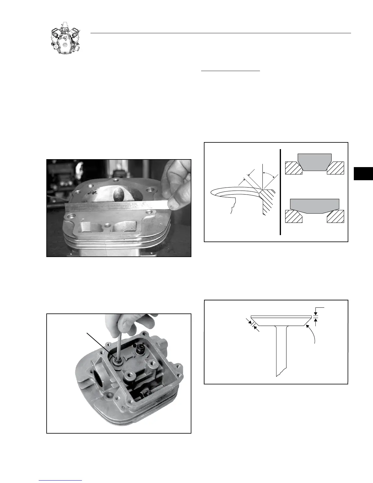
INSPECT AND REPAIR
1. Check cylinder head (Figure 5-7). Be sure all gasket material is
removed from surfaces before checking.
a. Inspect cylinder head for cracks or damage.
b. Use a surface plate or straightedge and check cylinder head
mounting surface for distortion.
If mounting surfaces are distorted more than 0.1 mm (.004"), the
cylinder head must be replaced.
Note: It is not recommended that cylinder head mounting surfaces
be resurfaced.
Figure 5-7. Check Cylinder Head Distortion
2. Clean the valve guides and measure their I.D. using a split ball
bore gauge (Figure 5-8).
a. Replace head if either valve guide measures 7.06 mm (0.278 in.)
or more. Valve guides should not be replaced.
SPLIT BALL
BORE GAUGE
Figure 5-8. Check valve guides
REFACE VALVES AND SEATS:
1. Valve seats may be reconditioned using a valve seat cutter.
If valve seat is wider than dimension shown in Figure 5-9, a
narrowing cutter should be used to ensure that contact area
of valve seat is centered on face of valve (see Figure 5-10).
a. Use a 60° cutter to narrow seat from bottom and a 15° cutter to
narrow seat from top (Figure 5-9).
Note: If valve seat is loose or cracked, replace cylinder head.
0.8 MM TO 1.2 MM
(1/16” - 3/64”)
60° CUTTER
44°
15° CUTTER
Figure 5-9. Valve Seat Dimensions
2. Valve faces may be resurfaced to 45°. See Figure 5-10 for dimen-
sions for valves.
Note: In most instances it is more economical to replace the valves
than to reface them.
1/32”
MINIMUM
1.2 MM TO 1.6 MM
(3/64” - 1/16”)
SEATING AREA CENTERED
ON VALVE FACE
45° VALVE FACE ANGLE
Figure 5-10. Valve Dimensions
3. Measure valve stem diameter at specified distance from end of
valve, as shown in Figure 5-11.
Replace if less than 6.9 mm (0.272 inches), or if total clearance
between valve stem and valve guide exceeds 0.12 mm (0.0047
in).
5