SECTION 5: CYLINDER HEAD AND VALVES
5-4
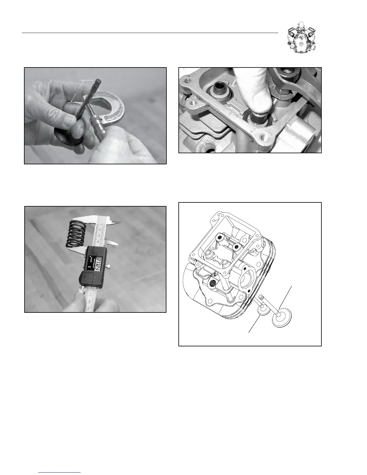
1.600” [40 mm]
Figure 5-11. Measure Valve Stem Diameter
4. Check valve springs for free length (Figure 5-12).
Replace if free length is less than 36.5 mm (1.437 inches).
Figure 5-12. Check Valve Springs
ASSEMBLE CYLINDER HEAD
1. Install new valve stem seals.
a. Press seal on to intake valve guide bushing until it bottoms (Figure
5-13).
b. Lubricate inner top lip of valve stem seal with oil.
Figure 5-13. Install Valve Stem Seals
2. Install valves (Figure 5-14).
Note: Lightly coat valve stems with oil before installing valves. Be
sure lubricant is not on valve face and seat.
EXHAUST VALVE
INTAKE VALVE
Figure 5-14. Install Valves
3. Place a shop rag or short section of rubber fuel line under valves
inside combustion chamber to hold valve in place while compress-
ing spring.
4. Install valve springs and valve spring retainers over valve
stems.
5. Compress valve spring and install keepers (Figure 5-15).