SECTION 5: CYLINDER HEAD AND VALVES
5-5
Figure 5-15. Compress valve spring and install keepers
6. Repeat procedure for other valve(s).
7. Set push rod guide plate in place with tabs facing upward, and
loosely install rocker arm assemblies (ball stud, rocker arm and
jam nut).
8. Repeat Step 7 for other head.
INSTALL CYLINDER HEAD
1. Install cylinder head with new gasket.
2. Torque head bolts in sequence shown to 29.9 Nm (22 ft.
lbs.) (Figure 5-16).
3. Insert push rods into recess in tappets.
A-B-
-D-E-
TORQUE SEQUENCE FOR HEADS:
Figure 5-16.
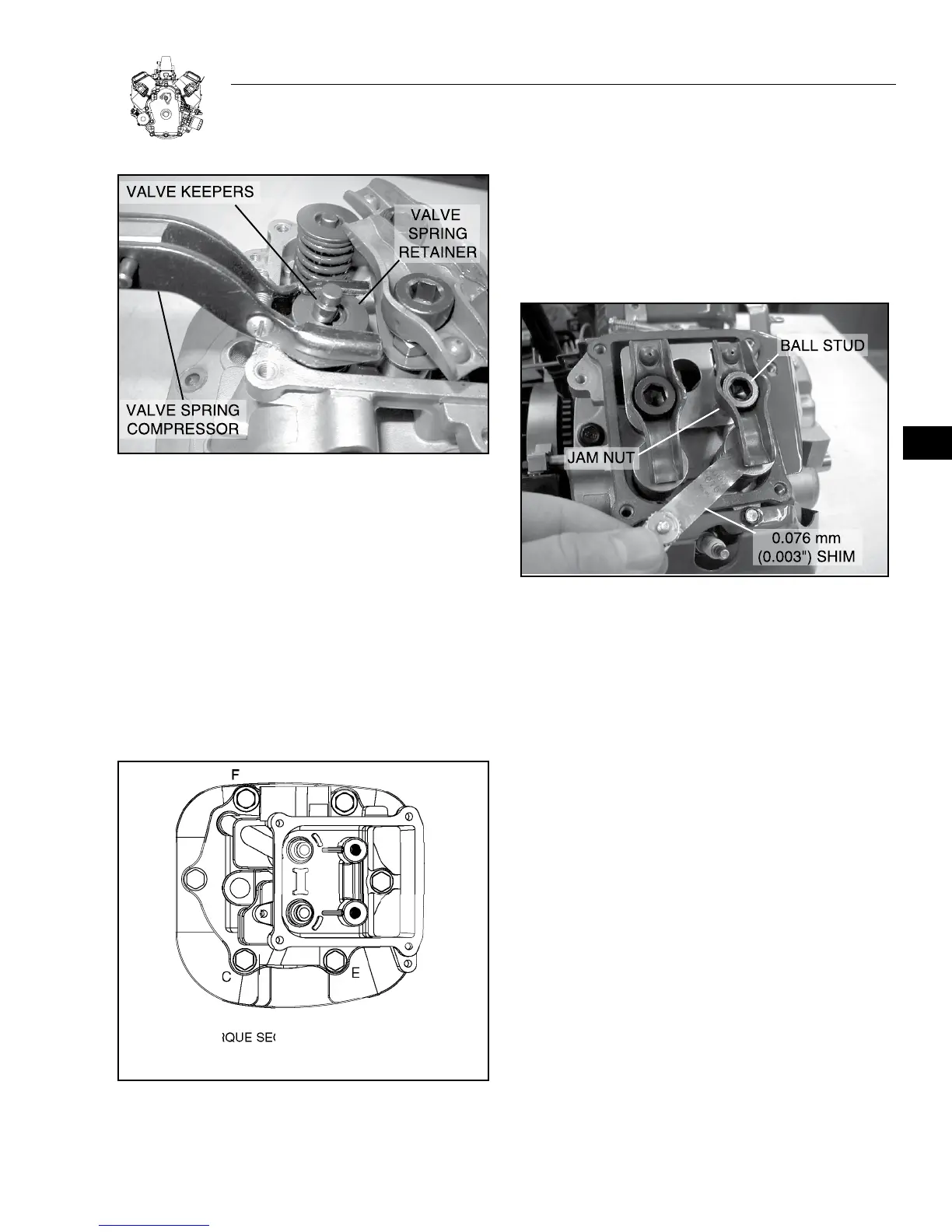
ADJUST VALVE CLEARANCE
1. Set No. 1 cylinder at TDC, compression stroke.
a. Adjust rocker arms and check clearance (Figure 5-17).
Valve Clearance (cold) Intake and Exhaust 0.076 mm (.003“).
b. Torque jam nut to 19 Nm (168 in. lbs.).
Figure 5-17. Adjust Valve Clearances
2. Set No. 2 cylinder at TDC, compression stroke and repeat Steps
1a and 1b above.
3. Install valve covers with new gaskets.
a. Torque screws to 6.8 Nm (60 in. lbs.).
REASSEMBLE
Install all parts shown in Figure 5-18.
1. Install cylinder wrappers.
a. Torque M5 screws to 2.8 Nm (25 in. lbs).
b. Torque M6 screws to 4.5 Nm (40 in. lbs).
2. Install spark plugs.
a. Torque to 19 Nm (168 in. lbs.).
3. Install exhaust manifold.
a. Torque screws to 19 Nm (168 in. lbs.).
4. Install blower housing.
a. Torque screws to 4.5 Nm (40 in. lbs).
5. Install intake manifold with new gaskets.
a. Torque screws to 19 Nm (168 in. lbs.).
b. Assemble governor link to carburetor.
5