EasyManuals Logo

Generac Power Systems GTH990 User Manual

Generac Power Systems GTH990
74 pages
To Next Page IconTo Next Page
To Previous Page IconTo Previous Page
Page #36 background imageLoading...
Page #36 background image
SECTION 5: CYLINDER HEAD AND VALVES
5-6
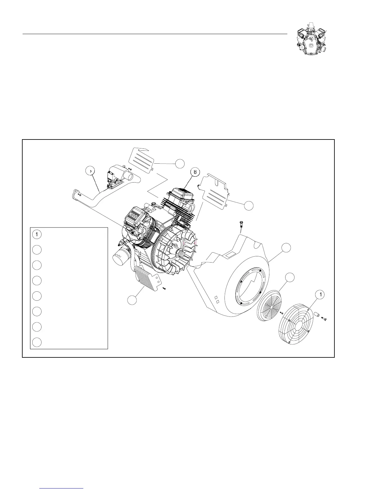
6. Install rotating screen.
a. Torque screws to 1.9 Nm (17 in. lbs).
7. Install finger guard.
a. If engine is equipped with hex head screws, torque screws to
4.5 Nm (40 in. lbs).
b. If engine is equipped with finger screws, tighten screws by hand
to approximately 1.3 Nm (12 in. lbs.).
8. Assemble air cleaner.
9. Make Static and Dynamic Governor adjustments as outlined on
Page 4-3.
1
2
5
7
6
3
4
1
2
3
4
5
6
7
8
8
VALVE
CO
VE
R
L
O
WER WRAPPE
R
U
PPER WRAPPE
R
BL
O
WER H
OUS
IN
G
O
IL
COO
LE
R
INTAKE MANIF
O
LD
A
SS
EMBL
Y
R
O
TATIN
G
SC
REE
N
FIN
G
ER
GU
AR
D
Figure 5-18. General Assembly

Questions and Answers:

Question and Answer IconNeed help?

Do you have a question about the Generac Power Systems GTH990 and is the answer not in the manual?

Generac Power Systems GTH990 Specifications

General IconGeneral
BrandGenerac Power Systems
ModelGTH990
CategoryEngine
LanguageEnglish

Related product manuals