SECTION 2:
IGNITION
SECTION CONTENTS
PAGE
sPEClFlCATIONS..................
-..... --------------....-....
2-1
GENERAL
lNFORMAT|ON..... ...........................................
2-1
ARMATURES
Armatur€Testing................-.....................----..-.........2l
Removing
Amatures ........................-.......................
2_1
lnstall
Armatures -................ .....................................-.
2-1
Adjusi Armaturc Air Gap ..........................................
2-2
FL\1/VHEEL
Remove Flywheel ..-...................................-...............2_2
lnspect Flylvheel
Key and Keylv ays ...........-................
2"2
lnstallFlylvhee1..........................................................2_3
ENGTNE
WtRTNG HARNESS .....................-......................
2-3
Tesling Grcund Wircs............................................-...
2-3
Engine wirlng Harness Diagram
................................
2-4
Diode Failurc Diagnosis
...-.--.....................................
2-4
SPECIFICATIONS
FOR
GW-990/760
0HVt V-TW|N ENGINE
MODEL 5ERLE5 ................................................Gry-990t60
ARMATURE AIR GAP.....................................008',
TO .012'
(.20TO.30
MM)
FLYWHEEL NUI TORQUE
n: 185..........--......................
..
.. - - .......150
FL\1/VHEEL NUT TORQUE
NM............__.......................................-......................203.0
See Section
1 For Spatk PIug MainFnan.e
And Spe<ifi<ations
GENERAL INFORMATION
Generac
GTV-990,60 OHVIV-Twin
engines use a
magneto
ignltionr an
ignition amalure with a
seli-contalned transistor
module
(no
moving
paats).
Two magneto
ignition arrnatures
are used, with a flyljvheel
containing a
permanent
magnet.
NOTE:
fhe magneto ignition
synem rcquires a minimum
of 350
RPM to
ptoduce
a consistent
spa*.
ARMATURES
ARMATURE TESTING:
The condition
of lhe ignition armatures
can be accu€tely
diag'
nosed using
an ignition testet,
(Generac
P/N 0C5969) as
desc bed in
'Trcubleshoot
n9' in Section
1.
REMOV NG
ARMATURES:
1.
Remove spark
plug
leads.
2.
Remove intake manifod
and covel
intake
pofts.
3. Remove rotating
screen
and blower housing.
4. Remove
armature screws and lift off armature(s),
Figure 2-1.
a. Disconnect
stop swltch
wires
at armatures.
Note:The
flwheel does
not need to be rcmoved to ser-
vice ignition
except
to check the flwheel ket.
INSTATL
ARMATURES:
1- Turn
fylvheelso magnet
is away frcm amatur€.
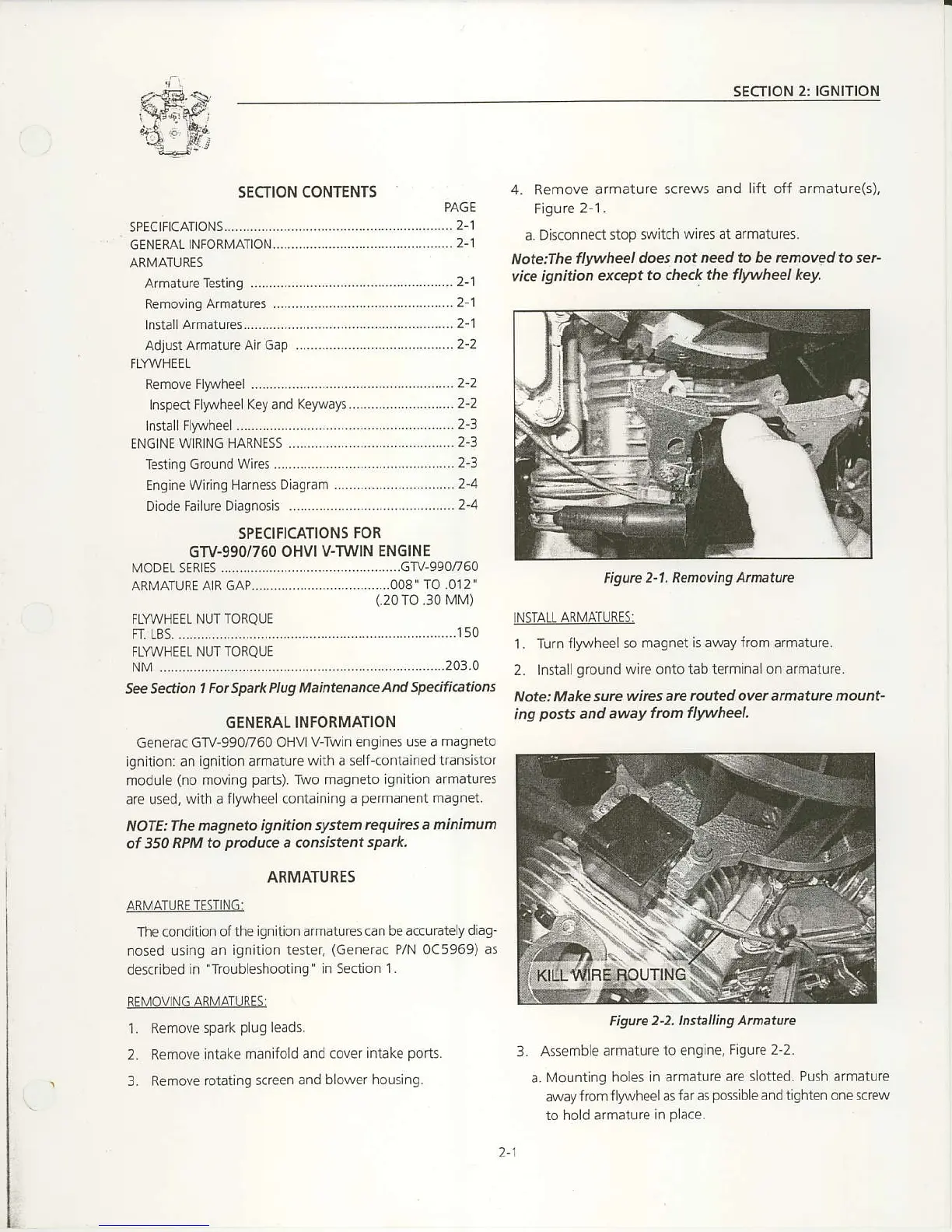
2. Install
ground
wire onto tab terminalon armature.
Note:
Make sure wires
are routed over afinature mount-
ing
posB
and away
lrcm flwheel.
figute
2-2. Ins|.jrlling Anaturc
3.
Assembe armature
to engine,
Figurc 2-2.
a.
Mounting holes in armature
are slotted, Push armature
away from
fly\,vheel as far as
possible
and tighten one sc€w
to hold afmaturc
in
place.
Figurc
2-1. Renoving Amature
2-1

 Loading...


