SECTION
13: ENGINE ASSEMBLY
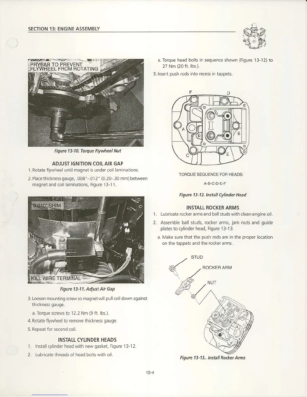
a. Torque head bolts
in
sequence shown
(Figure
13-12) to
27 Nm
(20
ft. lbs.).
3.lnsen
push
rods into
recess
in tappets.
ADJUST IGNITION COILAIR 6AP
'LRotate
flylvheel until magnet is under coi
laminations.
2.Placethickness9au9e,.008"-.012'
{0.20-.30
mm)
between
magnet and coil laminations, Fig ure l 3- 1
.I
.
TORQUE SEOUENCE FOR HEADS:
A.B,C,D.E.F
Figwe 13'12lnsli Cylinder Head
INSTALL ROCKER ARMS
1. Lu bricate rocker arms and ballstuds with
clean engine oil.
2, Assemble ball studs, rccker arms,
jam
nuts and
guide
plates
to cylinder head,
Figu€ 13-l3.
a.
Make
surc that
the
push
rods are in the
proper
location
on the tappeti and the
rocker
arms.
3. Loosen mounting
screw so
magnet will
pull
coil down against
thickness
gauge.
a. Torque screws to l2-2 Nm
(9
ft. lbs.).
4. Rotate fll1,1/heelto
emove thickness
gauge.
5,Repeat for second coil.
INSTATI. CYLINDER HEADS
1. Installcylinder head with new
gasket,
Figure 13-12.
2.
Lubricate
threads of
head
bolts
with
oil.
FOCKER ARM
Figwe 13-10. Torque Flwheel
Nut
@".fr
nilil
@r,<
\
/B
Figute 13-11. Adjust
Ak Gap
13-4
Figute 13-13.,lnstall Rod<et Ant

 Loading...


