SECTION 2: IGNITION
Figue 2-6, Che.k
Hwheel And eankshaft
INSTALL FL\ryVHEEL:
Note: CLEAN flwheel
and
(ankshaft
taper removing
all
oil, dirt or
gtease.
1.
Insertflylvheel key into crankshaft.
2. Align
keyways and assernble flylvheel to crankshaft.
3. Installwasher and
flylvheel nut.
a. Toque fly,vl/heelnut to
203.0 Nm
(150
ft.lbs.),
Fiqure 2-7.
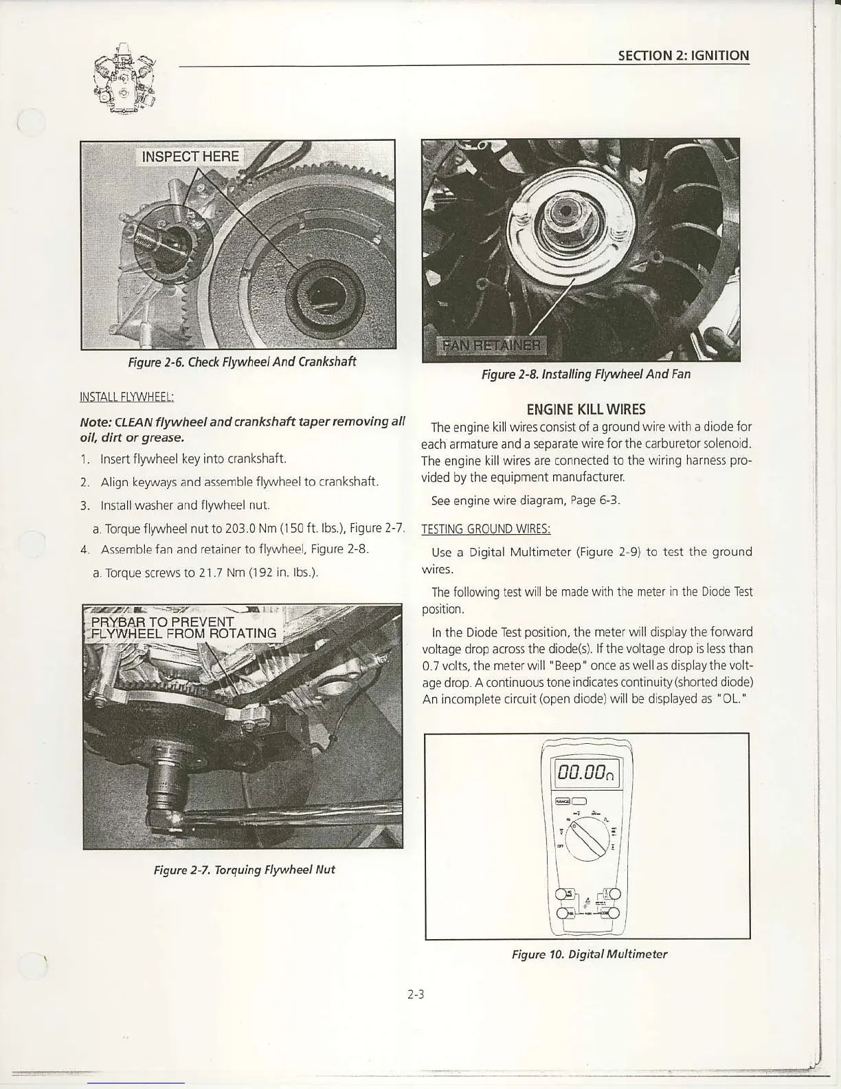
4. as5emblefan and retainerto
flywheel, Figure 2 8.
a.Torque screws to
2l.7 Nm
(192ln.
lbs.).
Figure 2-7,
Totquing Flwheel Nut
Figurc 2-S.lnsta ing Flywheel And
Fan
ENGINE KILL WIRES
The
engine
kill wires conslst of a
grcund
wire with a diodefor
each armatureand
a separate wire for the carbu retor solenoLd.
The engine killwires are connected
to the wirlng harness
pro-
vided by the equipment manulacturer
See engine
wire diagram,
Page 6-3.
TESTiNG GROUND WIRES:
Use a
Digital Multimeter
(Figure
2-9) to test the
ground
wires.
The iollowing test w
llbe made with the meter in the Diode Ten
In the Diode
Test
position,
the meter will display the foftvard
voltage drop acrcssthe
diode(s). lf the voltage drop is less than
0.7
volts, the meter will
'
Beep' once as
well
as display the
volt-
age drop.
A
continuous
tone indicates continuity(shoned diode)
An incomplete circuit
(open
diode) will be displayed as
'OL. '
2.3
Figurc 10. Digital Multinetel

 Loading...


