SECTION 5: CYUNDER
HEAO AND
VALVES
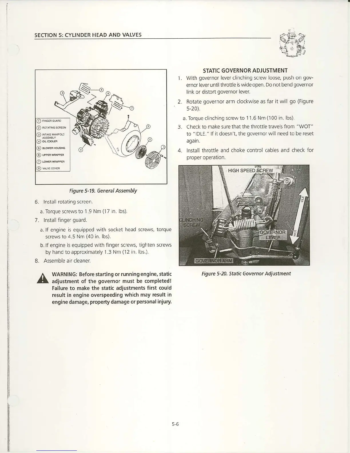
STATIC
GOVERNOR ADJUSTMENT
1. with
governor
lever clinching
screw loose,
push
on
gov-
ernor lever until
throttle is wide open, Do not bend
governor
link or distort
governor
lever.
2.
Rotate
governor
arm
clockwise as far it will
go (Figure
s-20).
a.Toque clinching
sc€w to 11.6 Nm
(100
in. lbs)-
3. Checkto make sure
that the throltle travelsfrom "WOT"
to
"IDLE." lf it doesnt, the
governor
will need to be rcset
again.
4. lnstall throttle
and choke control cables and check
for
proper
operation.
6. lnstallrotatingscrcen.
a. Torque screws to
1.9 Nm
(17
in. Tbs).
7. Install
finger
guard-
a. lf engine
is
equipped
with socket head screws,
torque
screws to
4.5 Nm
(40
in. lbs).
b.lf engine is equipped
with finger screws, tighten screvls
by hand to approximately 1.3
Nm
(12
in. lbs.).
8. Assemble
aircleanet
WARNINGT Before starting or
running engine, static
adjustment o{ the
governor
must be completedl
Failure
to
mak€ th€ static adjustments
first could
nesult in engine oversp€eding
whi6 may result in
engine damage,
property
danage or
personal
injury
Figwe
5'20. Static Govetnot Adjustment
Figve ,19. Genenl
attenbly
5.6

 Loading...


