SECTION 7: ALTERNATORS
SECTION CONTENTS
PAGE
20 ANlP REGULATED
ALTERNATOR ....._......................... 7-1
Alternator OutpUt Ten .-............................................ 7-1
Testing DC Output Charging W]re.............................. 7l
Testing Regulator-Reclifier....-----...........-.--...-...... 7-2
20 AMP REGULATED ALTERNATOR
The 20 amp regulated alternatorsystem
provideg
aC
current
through two
output leads to the regulator-rectlfier The regu-
latorrectifier
converts the AC currentto DC, and regu lates the
currenttothe bauery.
The
charg
ng rate willvarywith
engine
RPM and terirperature.
The stator, regulator-rectifier and flylvheel are NOT inteF
changeable
with any other alternator system.
WHEN CHECKING THE ALTERNATOR COMPONENTS,
MAKE THE IESTS IN THE FOLLOWNG SEQUENCE:
ALTERNATOR
OUTPUT TEST:
Temporarily, disconnect stator wire harness {rom regulator-
rectif er.
1. Insen RED test
lead into
vQ+l-
receptacle in meter.
2. lnserl ELACK test
lead into
EEU
receptacle in meter.
3.
Rotite selector to
v-
(AC
volts)
pos
tlon.
4. Attach
RED
and ELACKtest lead
probes
to AC outputter-
minals
(white
wiret, as shown in Figure. 7-1.
(Meter
test
cllp eads
may
be attached to either AC outputteminal.)
5. With the engine
running
at 3600 RPM output should be
no Less man:
26 Volts
-
20 Amp System
6.
lf no
o'low
oJtpJr r,
fould. (hec(
ror
bare
wi'e5
o'a.]y
other obvlous defects.
lf
'shoded'
leads afe not visible,
replace
the stator
TESTING DC OUTPUT CHARGING
WIREI
Asimple test
may
be
performed
to
testthe
DC
outputcharg-
ing wire circuit.
lf a
p.oblem
exists in the wi.ing il
can be
corrected before testing
regulatoFrcctifier
Leave stator
wirc hamess disconnected from regulatoFrec-
tifier
Equipnrent keyswitch must be
in
OFF
position.
I Insert RED test lead into vot1- receptacle in meter
2. Insert BLACK test lead into
@
receptacle ln meter.
3. Rotate selector to
V
(Dc
volts)
posiuon.
4. Attach RED test
lead
probe
to
DC
output wire terminal,
Figure 7-2.
5.
Attach SLACKtest lead
probeto
negatlve battery terminal.
6. Turn equipment
keyswitch to ON
position.
Meter
should
d splay battery
voltage.
7. lf meter does not dlsplay battery
voltage,
check for blown
fuse or broken or shorted
wires,
CAUTION: ATTACH
METER TEST LEADS TO aC
OUTPUTTERMINALS
(WHITE
WIRES) BEFORE
START.
ING ENGINE.IF STATOR IS GROUNDED
(DEFECNVE),
AND METER
TEST LEADS CONTACT CENTER DC
OUTPUT
PIN, ARCIN6 MAY OCCUR WHICH MAY
DAMAGE WIRING.
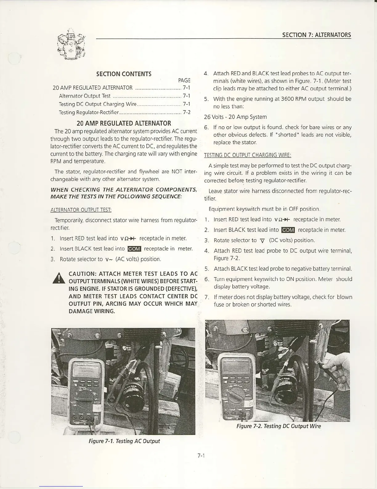
Figure 7-2,Iesting DC Out4ut Whe
Figurc 7-1. Teting AC
Output
7-1

 Loading...


