SECTION
12: PISTON, RINGS & CONNECTING ROD INSPECTION & ASSEMBLY
Figute l2-4. Che&ing Ring End Gap
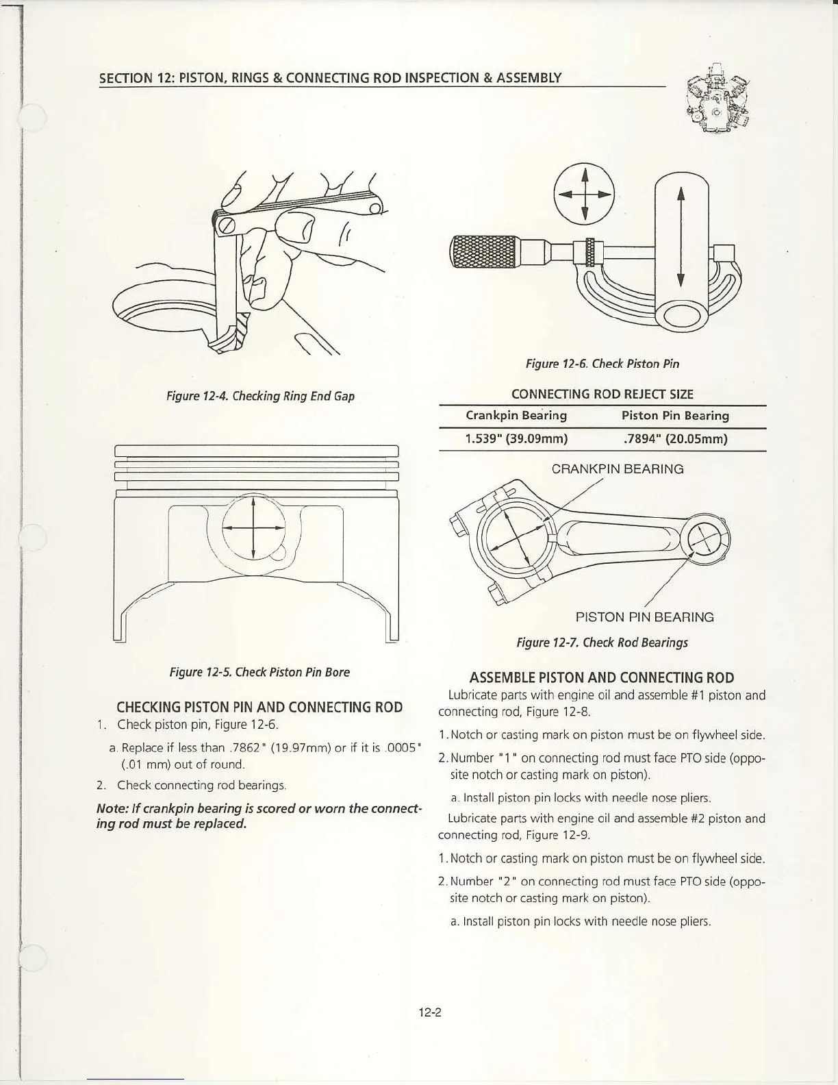
Figure 12-6. Check Piston Pin
CONNECTING ROD REJECT SIZE
Crankpin
Bearing Piston Pin Bearing
1.539"
(39.09mm)
.7894'
(20.05mn)
Figute l2-5. Ched< Piston Pin Eote
CHECKING PISTON PIN AND CONNECTING ROD
1-
Check
piston
pin,
Figure 12-6.
a. Replace if less than .7862'
(l9.97mnr)or
if it is .0005'
(.01
mm) out of round.
2. Check connecting
rod
bea ngs.
Note: ll ctankpin bearing is s.orcd or won the.onne.t-
ing rcd must be tepla.ed.
PISTON PIN BEARING
Figure l2-7, Check Rod Beaingt
ASSEMBLE PISTON AND CONNECTING ROD
Lubric:te
parts
with engine oil and assemble *1
piston
and
connecting rod, Figure
12-8.
l.Notch
or casting mark on
piston
must be on flywheeJside.
2-Number " 1
'
on
connecting
rod must face PTO
side
(oppo-
site
notch
or casting mark on
piston).
d l,rstallpinon
pi,r
locG with needle rose
pliers.
Lubricate
parts
with engine oil and assemble #2
piston
and
connecting rod, Figure 12-9.
l.Notch
or casting mark on
piston
must be on fly\,vheelside.
2.Number
'2'
on connecting rod mustface PTO side
(oppo-
site notch or casting mark on
piston).
a.Installpiston
pin
locks with need
e
nose
piiers.
CRANKPIN
BEAFING
12-2

 Loading...


