SECTION 13: ENGINE
ASSEMBLY
SECTION CONTENTS
lNsTALL CRANKSHAFr ............__........................_.........
13-1
|NSTALL PISTON AND CONNECTTNG
ROD .................... 13-1
tNsTALL CAMSHAFL............_....._...................____.........
t3-2
tNSTALL CRANKCASE COVER .._.......................__..........
13-2
GENERALASSEtV8LY.................__.................................
t3-3
tNsTA11 8REATHER ......................................................
13-3
|N5TALLFL\1|/HEEL.......................
............13-3
ADJUST tGNtTtON COtL AtR GAP..................................
13-4
tNSTALL CYLTNDER HEADS ............................................
13,
ADJU5TVA1VE5............................._..............................
13-
INSTALL CRANKSHAFT
Lubricatemagbearingandlipsof
oilsealwithengineoiland
installcrankshaft.
Figure 13-1.
Insta ing Qankhaft
INsTATL
PISTON AND CONNECrING ROD
Note: lnstall
*t
pinon
and connecting rcd tiEL
1 - Oil
piston
ngs,
piston
skift, and compress rings with Ring
Comprcssor, Figure
l3-2.
a.
Place
piston
and ring compressor upside down
on bench
with
projedions
on comprcssor facing
up.
b.Tlghten ring
compressor evenly until rings are fully
com-
pressed.
c. Then loosen ring compressor very
slightly so th:t com
pressor
can be
rotated
on
piston
skirt while holding
connecting rcd, Figure 13-2.
d, Remove connecting rod cap.
Figure 13-2. Conpresting Rings
2. Lub cate cylinder borcs and crankpin and rotate
crankhaft
until it is at bottom of stroke.
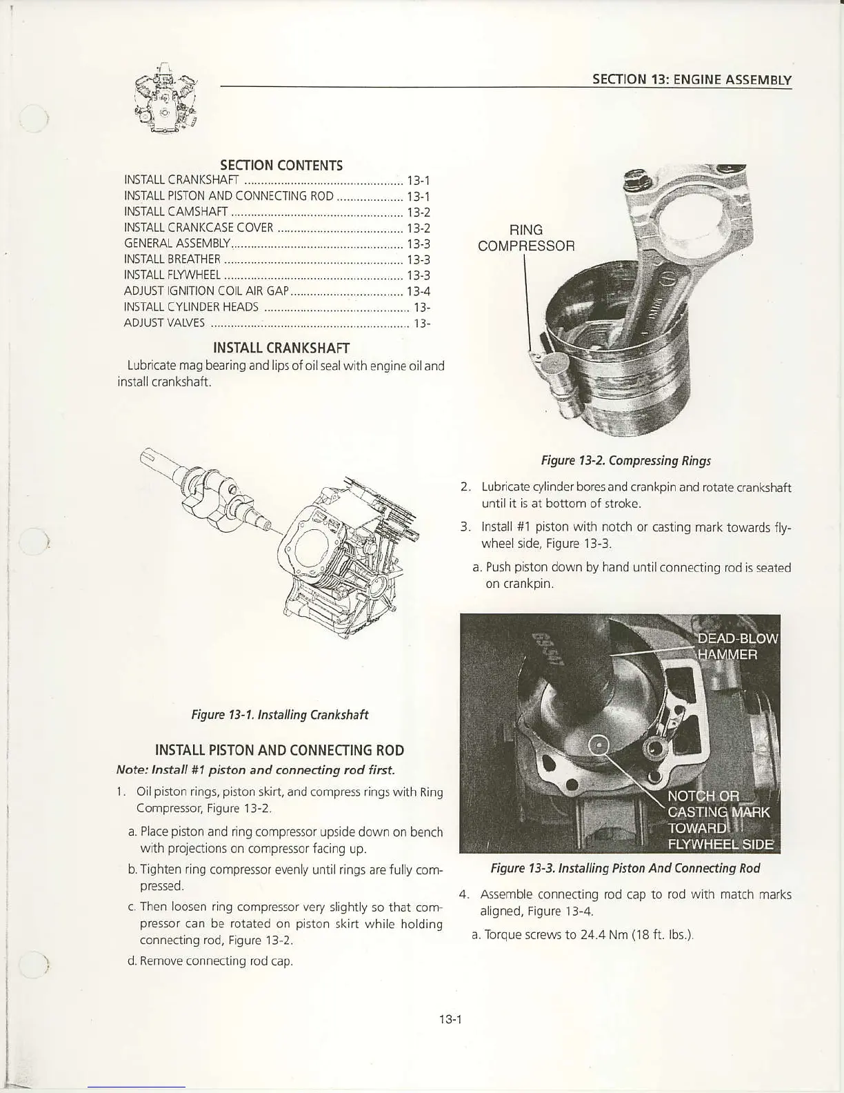
3. Install #l
piston
with notch or
casting mark towards fty-
wheelside, Figurc 13-3.
a.
Push
piston
down
by hand untilconnecting rod
is seated
4. Assemble
connecting rod cap to
rod with
match marks
allgned, Figure 13-4.
a. Torque screws to 24.4 Nm
(18
ft. lbs.).
FIING
COMPFESSOB
Figure 13-3, lnsElling Piston And Conneding Rod
13-1

 Loading...


