Operation
26 MMG25I-35D-45I-55DF4 Operating Manual 36949 B
DANGER
IMPROPER OR INCORRECT CONNECTIONS TO A BUILDING’S ELECTRICAL SYSTEM
CAN CAUSE POTENTIALLY LETHAL VOLTAGES TO BACKFEED INTO UTILITY LINES.
THIS MAY RESULT IN INJURY OR ELECTROCUTION TO UTILITY WORKERS NEARBY.
VERIFY THE GENERATOR IS SUPPLYING POWER TO AN ISOLATED OBJECT OR
BUILDING THAT IS NOT CONNECTED TO ANY UTILITY LINES.
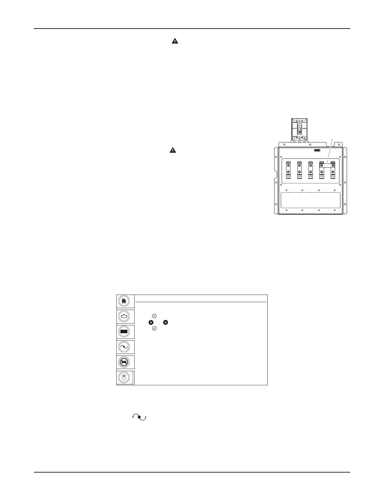
Connections to the lugs should be made by running the power cables up through the
opening in the bottom of the box. DO NOT make any connections directly to the lugs
without routing the cables through the opening. Use a hex wrench to tighten the cable
connections. The connection lug door is equipped with a safety interlock switch that
will trip the main circuit breaker and disable the voltage regulator, if the door is opened
while the unit is operating.
WARNING
Never attempt to disable or modify the lug door safety switch.
Equipment damage, personal injury or death may result.
A ground connection is located next to the connection lugs. The unit MUST be
connected to ground for proper operating safety. The generator neutral is bonded to
ground when it is shipped from the factory. The bonding plate will need to be removed
when the generator is used as a standby power source. INSTALLATION SHOULD
BE IN COMPLIANCE WITH THE NATIONAL ELECTRICAL CODE (NEC), STATE
AND LOCAL REGULATIONS.
Figure 3-4. Bonding Plate
Location
FINE VOLTAGE ADJUSTMENT
Adjustment of the output voltage from the generator is necessary to provide the correct voltage to the end of the
power line. Voltage adjustment can be carried out at any time on the Voltage Adjust screen.
Figure 3-5. Voltage Adjust Screen
1. With the unit running, press .
2. Press . The voltages displayed will begin flashing.
3. Use ▲ and ▼ to adjust the voltage.
4. Press to confirm the new voltage. The voltages displayed will stop flashing.
RUN CABLE THROUGH
OPENING IN BOTTOM
OF LUG BOX
01032
Bonding
Plate
00396
Manual Mode
GEN
V
+
-
Voltage Adjust
- Press , voltage will begin flashing
- Use and arrows to adjust voltage
- Press to confirm new voltage. Numbers will stop flashing
L-N Average
L-L Average
480
277
V
+
-
 Loading...