Operation
36949 B MMG25I-35D-45I-55DF4 Operating Manual 31
1. Open the control door and locate the switch labeled “FORCE EXHAUST REGENERATION”.
2. Move and hold the switch into the position.
Enable Exhaust Filter Cleaning
If the environment no longer requires the function to be disabled and there are no alarms present on the DPF Status
screen, the auto exhaust filter cleaning function should be enabled. Use the following procedure to enable the auto
exhaust filter cleaning feature:
1. Enter the maintenance screens by pressing ▲, ►, ▼, or ◄.
2. Press and hold () to enter the Running Editor.
3. Press ▼ to move the cursor down to the Engine section.
4. Press () or ► to access the sections. Options should already be highlighted.
5. Press ► and then ▼ to highlight DPF Regen Inhibit. Press () to select the check box.
6. Press ▲ to unmark the check box.
7. Press and hold () to save the settings. The display should return to the Home screen.
8. Verify the Home screen no longer displays “DPF Regen Inhibit” above the kW meter and the load used
gauge.
TRANSFER SWITCH
The generator neutral is bonded to ground when shipped from the factory. The bonding
plate will need to be removed when the unit is used as a standby power supply. Installation
should be in compliance with the National Electrical Code (NEC), state and local regulations.
When the unit is used as a standby power supply, it must be equipped with a transfer switch which isolates it from
the utility’s distribution system. A transfer switch is designed to transfer electrical loads from the normal power source
(utility) to the emergency power source (generator) when normal voltage falls below a prescribed level. The transfer
switch automatically returns the load back to the normal source when power is restored back to operating levels.
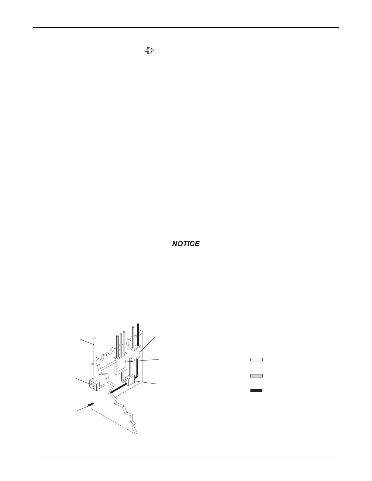
Figure 3-9. Transfer Switch Operation
Incoming
Utility
Power
Utility
Meter
Transfer
Switch
Main
Distribution Panel
(Utility Power)
Emergency
Distribution Panel
(Generator Power)
Power From
Generator
WHITE = Incoming
Utility Power
GRAY = Normal Utility
Power Circuit
BLACK = Emergency
Generator Power Circuit
00206
 Loading...