Owner’s Manual for Mobile Generator 7
General Information
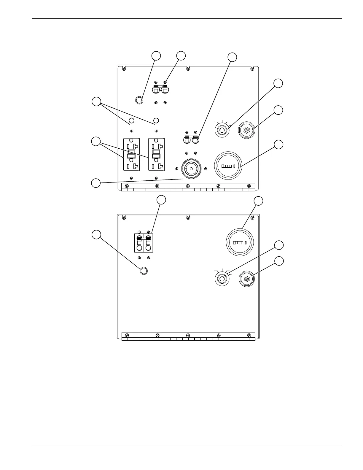
Main Control Panels
Figure 2-3. Control Panel Component Locations
Table 2-2. Control Panel Components
A
Circuit Breaker Indicator Light
F
Engine Hour Meter
B
Main Circuit Breaker
G
240V Twist-Lock Receptacle
C
240VAC Circuit Breaker
H
120V GFCI Receptacles
D
Key Switch
I
120V Breaker
E
Glow Plug Indicator
120VAC120VAC
120VAC120VAC
240VAC240VAC
TURNTURN
MAINMAIN
BREAKERBREAKER
OFFOFF
120VAC120VAC
BREAKERBREAKER
120VAC120VAC
BREAKERBREAKER
240VAC240VAC
MAIN CIRCUITMAIN CIRCUIT
BREAKERBREAKER
240VAC240VAC
BREAKERBREAKER
GLOW PLUGGLOW PLUG
INDICATORINDICATOR
OFFOFF
RUNRUN
STARTSTART
GLOWGLOW
PLUGSPLUGS
NEUTRAL BONDED TO FRAMENEUTRAL BONDED TO FRAME
I
O
I
O
ON
ON
20 20
0
0 00 0
HOURS
ON
ON
TURN MAIN
BREAKER OFF
MAIN
BREAKER
240V
OFF
RUN
START
GLOW
PLUG
NEUTRAL BONDED TO FRAME
ON ON
0 0 00 0
HOURS
MLG8
MLG15 • MLG20 • MLG20ICAN
 Loading...