8 Owner’s Manual for Generac PWRcell Battery
General Information
Component Locations
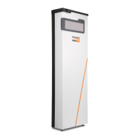
Figure 2-4. Component Locations
NOTE: PWRcell Battery IR model shown.
Accessories
Touch-Up Paint Kit
Maintains the look and integrity of the battery enclosure.
For more information, contact the nearest Independent
Authorized Service Dealer (IASD) or Generac Customer
Service at 1-888-436-3722 (1-888-GENERAC), or visit
www.generac.com.
Battery Disconnect Switch
See Figure 2-4. Battery Disconnect Switch (A)
disconnects the battery stack from the battery monitoring
system (BMS) electronics.
The Battery Disconnect Switch can be locked in the OFF
position if required. The switch bracket accepts a
standard lockout / tagout lock.
NOTE: Turn Battery Disconnect OFF whenever the
system will be powered down and left inactive for an
extended period of time to prevent battery discharge.
Battery Status LED
See Figure 2-4. The color and strobing interval of LED
(B) communicates battery status.
About PWRcell Battery
The PWRcell Battery is the storage component of the
PWRcell system. The battery can be used for grid-
connected solar applications, such as Self Supply, Rate
Arbitrage, and Clean Backup power. The battery is
designed to work seamlessly with PV Links and the
PWRcell Inverter to form the PWRcell system for grid-
tied solar-plus-storage.
The PWRcell Battery uses the REbus 380VDC nanogrid
to connect the PWRcell Inverter. The REbus nanogrid
automates the flow of power to enable plug-and-play
setup and operation of PWRcell equipment.
In Figure 2-5, a REbus-compatible PWRcell Inverter (E)
is directly connected to PV Links (B) and PWRcell
Battery (C) on REbus (D), the DC nanogrid/lines (D). To
the right of the inverter are AC lines: 240VAC or 208VAC
for grid and home loads (G), and protected loads (H).
Load support varies by model and number of battery
modules attached. Refer to Specifications for more
information.
A Battery Disconnect Switch
B Battery Status LED
C Intake Filter
D Front Cover
E Exhaust Vent
009890
C
D
E
B
A
(000600)
Electrocution. Initiate a system-wide shutdown and turn the
PWRcell DC Disconnect Switch OFF on all connected
batteries before performing service. Failure to do so will
result in death, serious injury, or equipment and property
damage.
Table 2-1. Battery Status LED
LED Color / Interval Battery Status
Orange, solid Disabled
Orange, strobe (2s) Waiting
Green / Orange, alternating Initializing
Green, solid Charging
Green, rapid blinking (0.5s) Discharging
Green, strobe (2s) Standby
Red, rapid blinking (0.5s) Error
Red, strobe (8s) Sleeping

 Loading...