Owner’s Manual for Generac PWRcell Battery 9
General Information
.
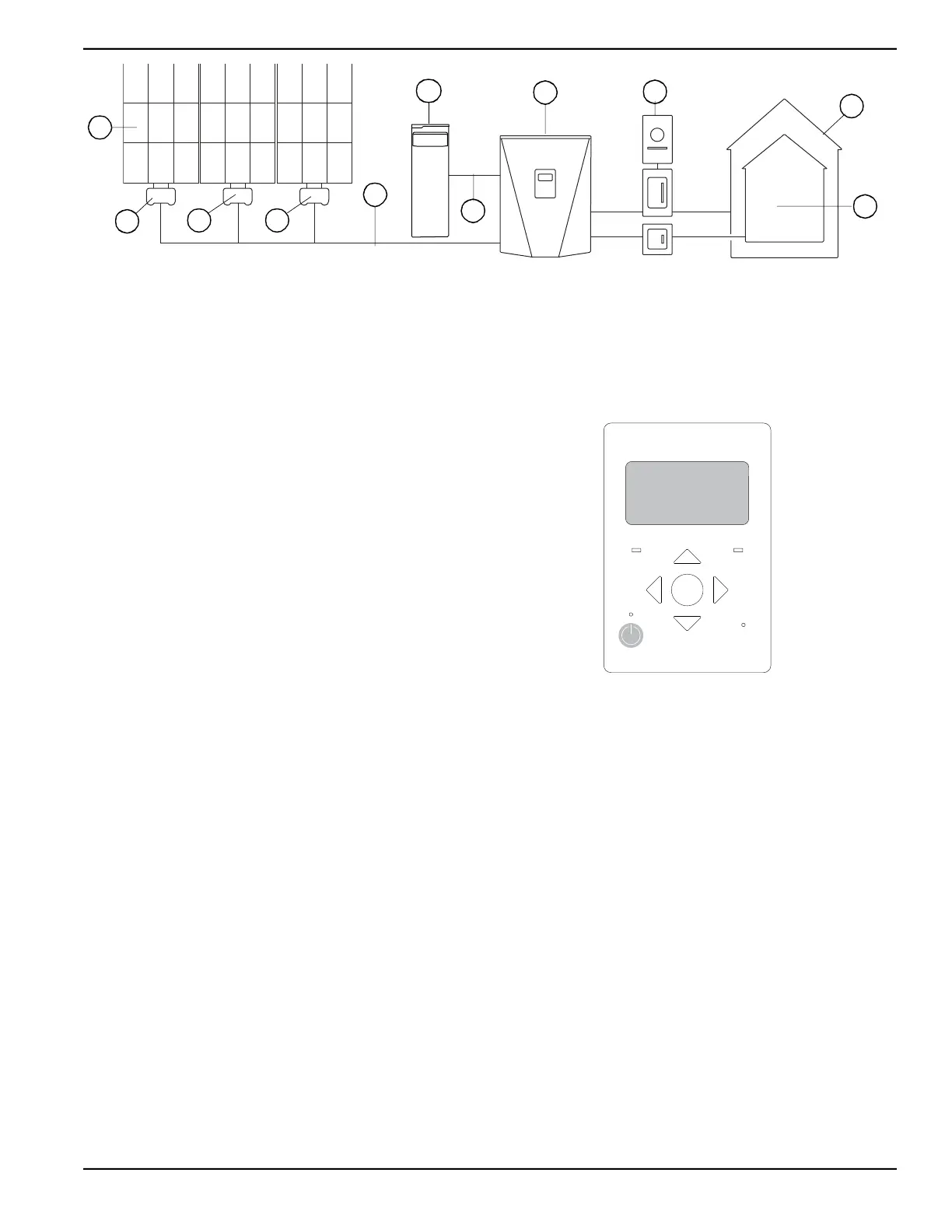
Figure 2-5. Generac PWRcell System Example
Communication
All communication between REbus devices takes place
over the REbus conductors using Power Line Carrier
(PLC) communication. No additional communication
wiring or equipment is required for communication
between a PWRcell Inverter, PV array, and / or other
REbus enabled batteries.
System Operational Modes
The PWRcell system has several operational modes
available for various installation configurations, markets,
and applications. Operational modes are selected
through the PWRcell Inverter control panel. The inverter
prioritizes the distribution of power differently based on
the selected operational mode.
See the Generac PWRcell Inverter installation and
operation manuals for complete instructions on
configuring the entire system for each operational mode.
Inverter Control Panel
See Figure 2-6. The battery is controlled through the
PWRcell Inverter control panel. Use the inverter control
panel to enable or disable the battery, and to set the
operational mode for the system. See the Generac
PWRcell Inverter Owner’s Manual for more information
on settings and display screens.
Figure 2-6. Inverter Control Panel
Battery State of Charge (SoC)
Setpoints
There are four user-adjustable setpoints related to the
battery state of charge (SoC): Min Absolute, Max
Absolute, Min Reserve, Max Reserve. These setpoints
are adjusted through the inverter control panel. See the
Generac PWRcell Inverter Owner’s Manual for more
information.
A Solar Panels E PWRcell Inverter
B PV Link F Grid
C PWRcell Battery G Loads
D REbus H Protected Loads
009893
A
C
D
E
F
G
H
B
B
B
D
REbus Inverter
Internet
Shutdown
(hold)
009894
 Loading...