Home
Generac Power Systems
Portable Generator
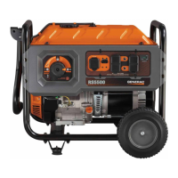
RS5500
Generac Power Systems RS5500 User Manual
5
of 1
of 1 rating
114 pages
Give review
Manual
Specs
To Previous Page
To Previous Page
Loading...
Part No. 0H2953
Rev.
F
05/16/2018
©2018 Generac Powe
r
Systems, Inc.
All rights reserved
Specifications ar
e
subjec
t
to
cha
nge
wi
thout
n
otice.
No reproduction allowe
d
in
any fo
rm witho
ut
prio
r
written
consen
t
from
Gene
rac Pow
er Systems,
Inc.
Generac Power Systems, Inc.
S45 W29290 Hwy
. 59
W
aukesha, WI 53189
1-888-GENERAC (1-888-436-3722)
www
.generac.
com
113
Table of Contents
Read this Manual Thoroughly
2
Replacement Parts
2
Rotor and Stator Resistance Tables
3
Table of Contents
5
Section 1 Brushless Capacitor Excitation
7
Introduction
7
Stator Assembly
7
Rotor Assembly
7
Operation
8
Troubleshooting Flowcharts
9
If Problem Involves AC Output
9
Problem 1 - Generator Produces Zero Voltage or Residual Voltage
9
Problem 2 - Voltage & Frequency Are both High or Low
10
Problem 3 - Excessive Voltage/Frequency Droop When Load Is Applied
10
Problem 4 - Generator Produces High Voltage at No-Load
10
Section 2 Direct Excitation (Brush Type)
11
Introduction
11
Stator Assembly
11
Brush Holder and Brushes
11
Voltage Regulator
11
Operation
11
Troubleshooting Flowcharts
13
If Problem Involves AC Output (Brush Type)
13
Problem 5 - Generator Produces Zero Voltage or Residual Voltage
13
Problem 6 - Voltage & Frequency Are both High or Low
14
Problem 7 - Excessive Voltage/Frequency Droop When Load Is Applied
14
Problem 8 - Generator Produces High Voltage at No-Load
14
Section 3 AC Diagnostic Tests
15
Test 1 - Check No-Load Voltage and Frequency
15
Test 2 - Check Main Circuit Breaker
15
Test 3 - Check Continuity of Receptacle Panel
15
Test 4 - Fixed Excitation Test/Rotor Amp Draw Test
16
Test 5 - Field Flash Alternator
18
Test 6 - Check Capacitor
19
Test 7 - Test Brushless DPE Windings
19
Test 8 - Test Brushless Stator Windings
20
Test 9 - Test Brushed Stator Windings
20
Test 10 - Check Load Voltage & Frequency
20
Test 11 - Check Load Watts & Amperage
20
Test 12 - Adjust Voltage Regulator
21
Test 13 - Voltage Changeover Switch 120/240 Position
21
Section 4 EFI Engine Control Diagnostic Tests
23
Basic EFI Theory
23
Basic Open-Loop Theory
23
Engine Requirements
23
Fuel System
23
Air Metering and Measurement
24
Sensor Inputs
24
Basic Operation
24
EFI Fault Code Diagnostics
25
Section 5 Engine Diagnostic Tests
27
Diagnostic Flow Charts
27
Problem 9 - Recoil Cord will Not Pull (208/389/420/459Cc Engines)
27
Problem 10 - Engine Starts Hard and Runs Rough (208/389/420Cc Non-EFI Engines)
27
Problem 11 - Engine Turns over but will Not Start (208/389/420Cc Non-EFI Engines)
28
Problem 12 - Engine "Hunts" / Erratic Idle (208/389/420Cc Non-EFI Engines)
28
Problem 13 - Engine will Not Crank (220/410/530Cc Engines with Electric Start)
29
Problem 14 - Recoil Cord will Not Pull (if so Equipped) (220/410/459/530Cc Engines)
29
Problem 15 - Engine Cranks but will Not Start (220/410/530Cc Non-EFI Engines)
30
Problem 16 - Engine Starts Hard and Runs Rough (220/410/530Cc Non-EFI Engines)
31
Problem 17 - Engine Starts then Shuts down (220/410/530Cc Non-EFI Engines)
31
Problem 18 - Battery will Not Charge (220/410/459/530Cc Engines)
31
Problem 19 - Engine "Hunts" / Erratic Idle (220/410/530Cc Non-EFI Engines)
32
Problem 20 - Unit will Not Idle (220/410/426/530Cc Non-EFI Engines)
32
Problem 21 - Unit will Not Come off Idle (220/410/426/530Cc Non-EFI Engines)
32
Introduction
33
Test 14 - Check Fuse
33
Test 15 - Check Battery and Cables
33
Test 17 - Check START-RUN-STOP Switch (410/426Cc Engine)
34
Test 18 - Test OFF-ON Switch
34
Test 19 - Check Starter Motor
34
Test 20 - Check Ignition Spark
35
Test 21 - Check Spark Plugs
36
Test 22 - Check Carburetion
36
Test 23 - Choke Test
37
Test 24 - Check Valve Adjustment
37
Test 25 - Check Engine / Cylinder Leak down Test / Compression Test
38
Test 26 - Check Ignition Coil
39
Test 27 - Check Flywheel
39
Test 28 - Remove Shutdown Wire
40
Test 29 - Check / Adjust Governor (208/389/420Cc Non-EFI Engine)
40
Test 30 - Check / Adjust Governor (220/410/530Cc Non-EFI Engine)
41
Test 31 - Check Oil Pressure Switch
41
Test 32 - Check Oil Level Switch
42
Test 33 - Test Recoil Function
42
Test 34 - Test Engine Function
42
Test 35 - Test Battery Charger (Non-EFI Units)
42
Test 36 - Test Battery Charging Circuit (EFI Electric Start Models)
43
Test 37 - Test Idle Control
43
Section 6 Major Disassembly
45
Introduction
45
Section 7 Electrical Data
55
Introduction
55
Wiring Diagram and Electrical Schematic, RS5500 Drawing No. 0K6393-A
56
Wiring Diagram and Electrical Schematic, RS7000E Drawing No. 0K6394-C
60
Wiring Diagram and Electrical Schematic, XC6500 Drawing No. 10000010344-A
64
Wiring Diagram and Electrical Schematic, XC6500E/XC8000E Drawing No. 10000010343-A
68
Wiring Diagram and Electrical Schematic, XP4000 Drawing No. 0H8536-D
72
Wiring Diagram and Electrical Schematic, XP5600E & XP6400E Drawing No. 0K2042-A
76
Wiring Diagram and Electrical Schematic, XP6500E Drawing No. 0H6809-D
78
Wiring Diagram and Electrical Schematic, XP6500E Drawing No. 0H6809-D
81
Wiring Diagram and Electrical Schematic, XP8000E Drawing No. 0H7588-C
82
Wiring Diagram and Electrical Schematic, XP10000E Drawing No. 0H7214-D
86
Wiring Diagram and Electrical Schematic, XG4000 Drawing No. 0H3339-E
90
Wiring Diagram and Electrical Schematic, XG4000 Drawing No. 0H5278-A
92
Wiring Diagram and Electrical Schematic, XG5600E/XG6400E Drawing No. 0J8223-B
94
Wiring Diagram and Electrical Schematic, XG6500 Drawing No. 0H2780-F
96
Wiring Diagram and Electrical Schematic, XG7000E Drawing No. 0H3525-C
98
Wiring Diagram and Electrical Schematic, XG8000E Drawing No. 0H5145-A
100
Wiring Diagram and Electrical Schematic, XG10000E Drawing No. 0H3931-B
102
Wiring Diagram and Electrical Schematic, XT8000E Drawing No. 0K2800-C
106
Wiring Diagram and Electrical Schematic, HL6500E Drawing No. 0L2474-A
107
Wiring Diagram and Electrical Schematic, HL6500E Drawing No. 0K9434-B
109
Wiring Diagram and Electrical Schematic, HL6500E Drawing No. 0K9433-B
110
Wiring Diagram, XT8000EFI Drawing no
112
10000023894-A
112
Electrical Formulas
113
Other manuals for Generac Power Systems RS5500
Owner's Manual
32 pages
5
Based on 1 rating
Ask a question
Give review
Questions and Answers:
Need help?
Do you have a question about the Generac Power Systems RS5500 and is the answer not in the manual?
Ask a question
Generac Power Systems RS5500 Specifications
General
Brand
Generac Power Systems
Model
RS5500
Category
Portable Generator
Language
English
Related product manuals
Generac Power Systems RS7000E
114 pages
Generac Power Systems RD015
60 pages
7500EXL Rated watt Extended Life Generator
20 pages
Generac Power Systems 7500
20 pages
Generac Power Systems iQ3500
72 pages
Generac Power Systems GP2200i
68 pages
Generac Power Systems GP2500i
68 pages
Generac Power Systems GP3300i
68 pages
Generac Power Systems GP3000i
68 pages
Generac Power Systems 7000exl
24 pages
Generac Power Systems XT8500EFI
80 pages
iX1600 iX SERIES
2 pages