*
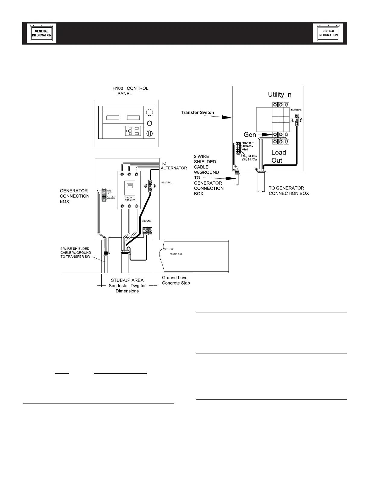
*Ground shield on one end only.
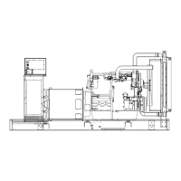
Figure 1 — Interconnections
6-2
Standby Generator Sets
Specifications
IGNITION DESCRIPTION
When this ignition is used on a 3.9L engine, a mag
pick-up sensor and 164 tooth flywheel are used
to determine engine timing. A Hall based CAM/
Distributor sensor establishes the location of fly-
wheel tooth number one. The 3.9L engine uses one
(1) coil driver together with a single-fire coil.
Nominal Engine Timing versus Engine Speed:
RPM LP Timing (BTDC)
1800 rpm 23 degrees
IGNITION POWER-UP INPUT ("56 LINE"
INPUT)
When battery voltage is applied to this input the igni-
tion will power up. For the ignition to power itself
down, battery voltage must be removed from this
input. When flywheel and cam pulses are no longer
detected by the ignition and this input is no longer
connected to plus battery voltage, the ignition will
power itself down.
FUEL SELECT INPUT
When this input is not connected (i.e. left open) the
ignition will operate in LP Fuel Mode.
IGNITION SHUTDOWN ON LOSS OF FLYWHEEL
OR CAM/DISTRIBUTOR SIGNALS
The ignition will stop firing the coils immediately fol-
lowing the loss of the flywheel signal. The ignition will
stop firing the coils approximately three (3) seconds
following the loss of the cam signal.
3.9L ENGINE SELECT INPUT
If this input is "low" when the ignition initially powers
up, the ignition will be configured for operation with
a 3.9L engine.
GenSpec015 Rev. 0 11/05