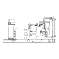
BASIC STANDBY ELECTRIC SYSTEM
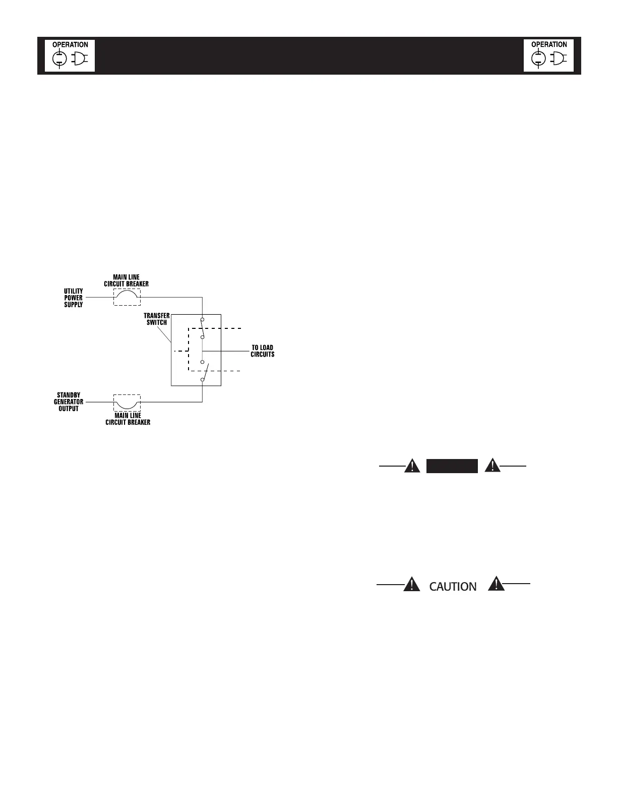
Figure 9.1 shows a schematic diagram of a basic
standby electric system. Both the UTILITY power
supply and the STANDBY (GENERATOR) output are
connected to an approved transfer switch. The trans-
fer switch is required by electrical code and serves
the following functions:
• Allows the LOAD circuits to be connected to only
one power supply at a time.
• Prevents electrical backfeed between the generator
and the UTILITY power circuits.
Figure 9.1 – Basic Standby Electric System
Notice that both the STANDBY and the UTILITY
power supplies to the transfer switch are protected
against overload by a main line circuit breaker.
STANDBY CIRCUIT ISOLATION METHOD
This prevents overloading the generator by keeping
electrical loads below the wattage/amperage capac-
ity of the generator. If the generator is powering only
designated loads, within the wattage/amperage capac-
ity, during utility power outages, consider using the
emergency circuit isolation method.
Designated electrical loads are grouped together and
wired into a separate “Standby Distribution Panel.”
Load circuits powered by that panel are within the
wattage/amperage capacity of the generator set. When
this method is used, it is difficult to overload the gen-
erator. The transfer switch must meet the following
requirements:
• It must have an ampere rating equal to the total
amperage rating of the standby distribution panel
circuit.
• Have it installed between the building’s main distri-
bution panel and the standby distribution panel.
TOTAL CIRCUIT ISOLATION METHOD
When a generator capable of powering all electrical
loads in the circuit is to be installed, use the “Total
Circuit Isolation Method.” It is possible for the gen-
erator to be overloaded when this isolation method is
employed. The following apply to the transfer switch
in this type of system.
• Ampere rating of the transfer switch must equal
the ampere rating of the normal incoming utility
service.
• The transfer switch is installed between the util-
ity service entrance and the building distribution
panel.
CONNECTION DIAGRAMS
All wiring in the standby electric power system must
be in strict compliance with applicable codes, stan-
dards and regulations. Such wiring must be properly
supported, routed, and connected. In addition, wir-
ing must be properly sized to carry the maximum
load current to which it will be subjected.
The connections between the generator and transfer
switch will vary depending on the equipment ordered.
In each case there are two types of interconnections,
load wiring and control wiring.
NOTE:
Control wiring must always be run in a separate
conduit from the load wiring.
DANGER
Make sure to turn OFF both the NORMAL
(UTILITY) and STANDBY (EMERGENCY) power
supplies before trying to connect power source
and load lines to the transfer switch. Supply
voltages are extremely high and dangerous.
Contact with such high voltage power sup-
ply lines causes extremely hazardous, possibly
lethal, electrical shock.
Be sure to maintain proper electrical clearances
between live electrical parts and grounded
metal. Allow at least one-half inch of clearance
for circuits up to 400 amps.
9-2
Standby Generator Sets
Operation
Oper008 Rev. 0 11/05