R
rashleyJul 31, 2025
What to do if the no load voltage frequency falls off on my Generac Power Systems XP8000E?
- KKim AlvaradoAug 1, 2025
First, verify that the rotor is spinning. Then, proceed to problem 3 for further troubleshooting steps.
What to do if the no load voltage frequency falls off on my Generac Power Systems XP8000E?
First, verify that the rotor is spinning. Then, proceed to problem 3 for further troubleshooting steps.
Manual for technicians, assumes familiarity with servicing procedures for Generac products.
Proper installation and tightening of components are critical to prevent ignition of fuel vapors from leaks.
Explains the 4 major components of a brushless generator: prime mover, stator, rotor, and capacitor.
Describes the stator's three windings: two power windings and one Displaced Phase Excitation (DPE) winding.
Explains the 2-pole rotor, its speed, diodes for AC to DC conversion, and North/South pole creation.
Explains startup, on-speed operation, and field excitation process for brushless generators.
Describes how maintained voltage is induced into stator AC power windings when loads are connected.
Guides users through diagnosing AC output problems using flow charts and AC diagnostic tests.
Troubleshooting flowchart for zero or residual voltage issues, directing to specific tests.
Introduces the 4 major components of a brush type generator: prime mover, rotor, stator, and voltage regulator.
Details the stator's three windings: two power windings and the DPE winding for excitation.
Describes the brush holder, positive/negative brushes, and their connection to the rotor windings.
Explains how the voltage regulator senses AC output and regulates DC excitation to the rotor.
Covers startup and on-speed operation, explaining voltage induction and speed-dependent voltage increase.
Explains how DPE winding, capacitor, and rotor interact to induce voltage and regulate output.
Explains how regulated voltage is induced into stator AC power windings when electrical loads are connected.
Guides users through diagnosing AC output problems for brush-type generators.
Troubleshooting flowchart for zero or residual voltage in brush-type generators.
Flowchart for diagnosing high/low voltage/frequency in brush-type generators.
Flowchart for diagnosing voltage/frequency droop under load in brush-type generators.
Flowchart for diagnosing high voltage at no-load in brush-type generators.
Procedure to measure AC voltage and frequency at no-load. Includes expected results.
Tests circuit breaker continuity using a DMM to ensure proper operation.
Checks receptacle continuity and physical connection to the stator, noting resistance values.
Tests rotor excitation and amp draw using a 12V battery and DMM.
Procedure to restore residual magnetism by applying voltage to the capacitor.
Checks capacitor value using a DMM and visual inspection for defects.
Tests the Displaced Phase Excitation winding resistance for continuity and shorts.
Tests stator windings for open circuits, shorts to ground, or shorts between windings.
Tests brushed stator windings for shorts to ground or chassis.
Tests generator voltage and frequency under load to ensure they are within limits.
Determines generator load capacity by checking wattage and amperage against limits.
Introduction to Electronic Fuel Injection, its history and use in portable generators.
Explains how EFI uses solenoid valves and ECU signals to control fuel delivery.
Discusses the importance of the correct air-fuel ratio for efficient engine operation and power.
Details the components of an EFI fuel system: tank, pump, regulator, and injector.
Explains how airflow is measured using a throttle body and pressure transducer.
Lists the 6 basic inputs measured by the ECU: RPM, Airflow, Manifold Pressure, etc.
Explains how the ECU processes sensor inputs to adjust injector pulse width for optimal operation.
Explains how to interpret fault indicator light flash codes for EFI system failures.
Guides users through engine diagnostic flow charts based on specific problems.
Troubleshooting flowchart for a recoil cord that will not pull on specific engine sizes.
Flowchart for diagnosing hard starting and rough running on non-EFI engines.
Flowchart for diagnosing engine starting issues where the engine turns but won't start.
Flowchart for diagnosing engine hunting or erratic idle issues in non-EFI engines.
Troubleshooting flowchart for electric start engines that will not crank.
Troubleshooting flowchart for recoil cord issues on specific engine sizes.
Flowchart for diagnosing starting issues where the engine cranks but won't start.
Flowchart for diagnosing hard starting and rough running in non-EFI engines.
Flowchart for diagnosing engine shutdown issues after starting.
Flowchart for diagnosing battery charging problems.
Flowchart for diagnosing engine hunting or erratic idle issues.
Flowchart for diagnosing issues where the unit will not idle.
Flowchart for diagnosing issues where the unit will not come off idle.
Procedure to inspect the fuse that protects the wiring and battery charger.
Tests battery voltage and checks for voltage drop in cables and connections.
Tests engine ignition system spark using a spark tester for proper operation.
Checks engine sealing ability and compression pressure to identify faults before disassembly.
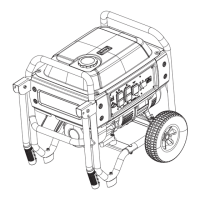
Introduces typical disassembly steps for removing fuel tank, stator, rotor, and engine.
Exploded view and parts list for the XC6500 generator.
Exploded view and parts list for the XC8000 generator.
Directs users to www.generac.com for the most current wiring diagrams and schematics.
Provides the wiring diagram and electrical schematic for the RS5500 model.
Provides the wiring diagram and electrical schematic for the XC6500 model.
Provides the wiring diagram and electrical schematic for the XP4000 model.
Provides the wiring diagram and electrical schematic for the XG4000 model.
Provides the wiring diagram and electrical schematic for the XG10000E model.
Provides the wiring diagram and electrical schematic for the XT8000EFI model.
Lists common electrical formulas for calculations related to kW, KVA, Amperes, Watts, Resistance, etc.
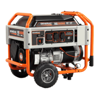
| Model | XP8000E |
|---|---|
| Type | Portable Generator |
| Starting Watts | 10000 |
| Rated Watts | 8000 |
| Running Watts | 8000 |
| Engine | Generac OHV |
| Engine Type | 4-Stroke |
| Engine Displacement | 420 cc |
| Fuel Type | Gasoline |
| Run Time at 50% Load | 11 hours |
| Voltage | 120/240V |
| Frequency | 60 Hz |
| Wheel Kit | Included |
| Weight | 200 lbs |
| Fuel Tank Capacity | 7.5 gallons |
| Outlets | 1 x 120/240V |
| Starting System | Electric/Recoil |