En-2
°C
NON STOP
CLOCK
TEMP
AUTO
TIMER
MODE
SET
ZONE
START/STOP
CLOCK ADJUST
SET TIME TEMP./DAY FAN
CONTROL
MASTER
CONTROL
21
HIGH
COOL
DEFROST TEST
DAY OFF
ENERGY SAVE
°C
NON STOP
CLOCK
TIMER
NEXT DAY
DAY
TEMP.
OFFON
TIMER
WEEKLY
AUTO
OFF
ON
OFF
ON
DAY OFF
21
HIGH
MED
LOW
AUTO
HEAT
FAN
COOL
DEFROST TEST
*
D
A
B 80
C 9 7
G
F
J
E
H I
Q
R
L
K
MNOP
5
6
6
5
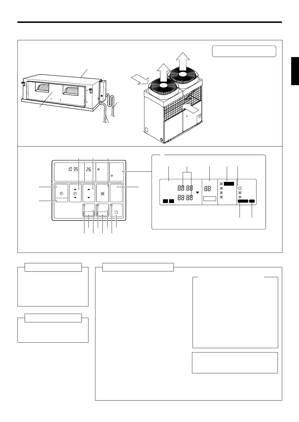
NAME OF PARTS
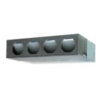
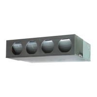
Fig. 1
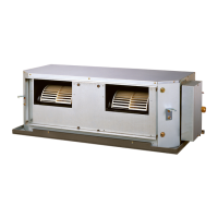
Fig. 2
Fig. 3
● For explanatory purposes, the figure showing the remote
controller display shows all possible displays. The actual
display shows only that area that is being adjusted or used.
Fig. 4 Display
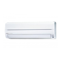
Fig. 1 Indoor Unit
1 Outlet Port
2 Intake Port
3 Drain Pipe (Main)
4 Drain Pipe (Safety)
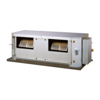
Fig. 2 Outdoor Unit
5 Air intake
6 Air outlet
Fig. 3 Remote Controller
7 START/STOP Button
8 Operation Lamp
9 ENERGY SAVE Button
0 DAY OFF Button
A ENERGY SAVE Lamp
B ZONE Control Button
C SET Button
D ZONE Control Lamp
E CLOCK ADJUST Button
F TIMER MODE Button
G SET TIME Button
H SET TEMP./DAY Button
#I FAN CONTROL Button
J MASTER CONTROL Button
K Remote Controller Display
(Fig. 4)
L Timer Mode Display
M Clock Display (CLOCK/TIMER)
N Set Temperature Display
(TEMP.)
#O Fan Speed Display
P Operation Mode Display
Q DEFROST Display
R TEST Display
Instructions relating to heating (*) are applicable only to “HEAT & COOL MODEL” (Reverse Cycle).
● Install this with the power sup-
ply chain during on-site instal-
lation.
#NOTE:
This model does not have a fan speed
function. (I, O)
Electrical Breaker
2
1
3
4
9365751046_OM_en.p65 11/4/08, 15:532