If the red and green LED shine at your CS121
HW131 during the reboot, huge broadcast traffic into
your network is present „recieve buffer overflow“.
The green LED is signalizing at the reboot, that the
„traffic buffer“ is full. Advice: You should filter
broadcasts via your switch, because it comes to
performance losing of the CS121 HW131
unnecessary.
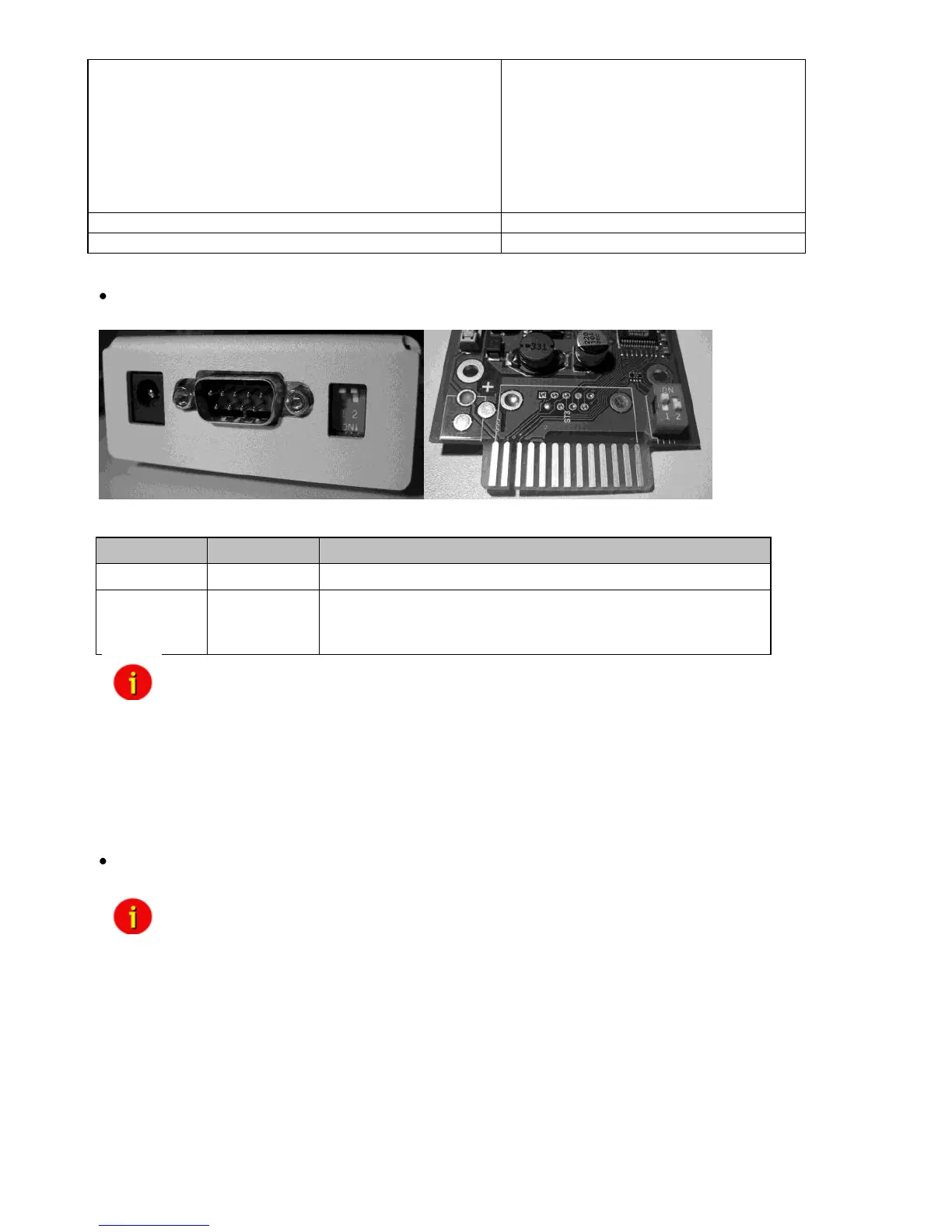
Note: In the configuration-mode the full functionality of the CS121 is not
provided! Please change to a valid network address and put DIP-switch
1 to position ON as soon as you made your basic network setting! After
this, please continue configuring your CS121 in your network. Please
follow up the procedure in chapter 2 Quickstart in this manual.
Additional information for CS121BL/CS121BSC: The BUDGET-versions do not have an
external connection for COM2. This configuration interface has been routed to COM1 (UPS
port).
(4) Power supply: A power supply adapter (wall socket unit) (DC, 12V) provides power for
the Adapter (external Model CS121L, CS121MOD, CS121BL only).
Note: If you are using a different power supply unit from the one in the adapter
package, please consider that the polarity is set correctly. The adapter
might be damaged if the wrong polarity is used. The power supply
voltage should be at least 9V, 12 V is recommended.
For the CS121SC models C and the slot card, there are no power supply
units. These units will receive power directly from the UPS device. The
SNMP adapter C and slot card both incorporate a variable 9-36V input.
UPS Interface cable (extern devices only): Please use the manufacturer’s serial port cable that
came with your UPS to connect the UPS with the SNMP-adapter. Please contact your UPS
manufacturer, if you have questions. Only use the original RS-232 UPS cable for
communication, which was provided with the UPS. If your UPS has a contact closure port,
please use the manufacturer’s special cable. Please consult your UPS dealer on information
regarding special cables.