English
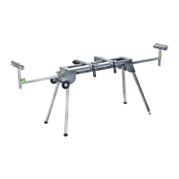
Miter Saw Stand
Operator’s Manual GMSS400W
To Remove Saw From Stand
1. Raise the locking levers to unlock the saw and mounting bracket assembly.
2. Lift away from the rear rail of the stand to disengage.
3. With the assembly titled slightly toward you, lift the front part of the assembly to disengage from the front rail
of the stand.
WARNING: The mounting brackets are designed to fit snugly over the stand
rails, with the locking levers in the lowered (locked) position, you should not be able to
remove the saw and bracket assembly from the rails. If the mounting brackets will not fit
over the rails, or if the mounting brackets can be removed from the rails when levers are
locked, remove from the saw and bracket assembly immediately and adjust the bracket
adjustment screw as described in the Adjustments section of this manual. Failure to heed
this warning may result in serious personal injury.
ADJUSTMENTS
BRACKET ADJUSTMENT SCREW (See FIG 8)
Mounting brackets are designed to fit snugly over the stand rails. With the locking levers in the locking position, you
should not be able to remove the saw and bracket assembly from the rails. If the saw and bracket assembly can be
removed form the rails when levers are locked, the bracket adjustment screws need to be tightened. If the saw and
bracket assembly will not fit over both rails, the bracket adjustment screws needs to be loosened.
NOTE: The saw should be removed from the mounting brackets before attempting to tighten or loosen the
bracket adjustment screws.
To Adjust:
1. Use a wrench to slightly loosen the nut (B3).
2. Turn the screw (B4) with a phillips screwdriver clockwise if the bracket assembly needs to be tightened, or
counterclockwise if the assembly needs to be loosened.
3. Install the bracket on the miter stand rails and lower the locking lever to check the adjustment.
4. When the correct position is achieved, wrench tighten the nut (B3) to secure.
5. Repeat with the second mounting bracket.
TO LEVEL STAND (See FIG 9)
The stand is equipped with an adjustable foot for leveling the stand.
To Adjust:
1. Use a wrench to slightly loosen the nut (A1)
2. Adjust the height of the foot by turning the threaded shaft (A2) clockwise to raise the foot or counter-clockwise
to lower the foot.
3. Retighten the nut (A1) securely.
WARNING: To reduce the risk of injury, make sure the stand is stable and
level before operating the saw. Choose a level area to set up the stand and adjust the
adjustable foot so that all four legs are touching the ground.
OPERATION
USING THE EXTENSION RAILS (See FIG 10)
Use the extension rails (2) when working with larger workpieces.
To Extend the Rails
1. Loosen the extension locking knob (6).
2. Extend the rail (2) to the desired position.
3. Tighten the extension locking knob.
8
 Loading...