Do you have a question about the Genesis SHERLOCK 102 and is the answer not in the manual?
Cautionary notes regarding risk of electric shock.
Warning about improper connection of external devices.
Details the purpose and compliance of the Sherlock monitor.
Introduces CMOS, Infrared, and Electro-Chemical sensors.
Explains the working principle and limitations of CMOS sensors.
Details the working principle of the infrared sensor.
Describes the Electro-Chemical sensor for ammonia detection.
Explains the Electro-chemical sensor for oxygen depletion.
Covers alarm setpoints, delays, and indications.
Details the function and types of alarm relay contacts.
Explains the setback feature for alternate environments.
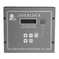
Describes the SHERLOCK 102/202 control module and its NEMA ratings.
Lists power, inputs, outputs, alarms, and environment specs.
Describes the IR sensor for refrigerant gas monitoring.
Details enclosure, dimensions, environment, and performance specs.
Lists part numbers for various refrigerants.
Outlines typical uses and critical warnings for IR sensors.
Explains dip switch settings for normal operation and testing.
Describes indicator lights and adjustment potentiometers.
Step-by-step guide to reset the IR sensor to factory settings.
General description of the CMOS sensor for refrigerant detection.
Lists accuracy, repeatability, environment, and output specs.
Part numbers for different gas types (CFC/HCFC, HFC, Ammonia).
Typical applications for CMOS sensors.
Details jumper pins, LEDs, and potentiometers.
Guidelines for correct sensor placement and mounting.
Minimum specifications for sensor cable runs.
Describes the sensor for vent line leak detection.
Lists dimensions, environment, power, and detection specs.
Details the high-pressure ventline sensor.
Lists enclosure, dimensions, and pressure specs.
Describes the sensor for ammonia gas monitoring.
Lists enclosure, dimensions, environment, and detection specs.
Describes LEDs, pushbuttons, and connectors on the sensor.
Describes the sensor for monitoring oxygen levels.
Lists enclosure, environment, power, and detection specs.
Instructions for proper mounting of the electrochemical sensor.
Instructions for performing zero calibration on the O2 sensor.
Details the specifications for the strobe light.
Describes the self-contained siren/strobe combination.
Lists enclosure, power, sound, and environment specs.
Details the stackable beacon appliance.
Describes the strobe light's visibility and housing.
Explains the remote alarm and remote alarm with strobe units.
Details the auto dialer's notification capabilities.
Describes the fail-safe remote alarm unit.
General placement advice for the monitor and sensors.
Specific placement for Halocarbon and Ammonia refrigerants.
Guidance on mounting sensors to walls or poles.
Requirements for sensor cable runs.
Placement advice for cycling exhaust fans.
Placement advice for piping troughs.
Placement advice for return air duct systems.
Rules for running sensor cables near power or inductive loads.
Guidelines for connecting sensor wires correctly.
Technical specifications for sensor cable types.
Diagram showing connections for the control module.
Details connections for COMM, SENSOR A/B, BUZZER, etc.
Visual guides for connecting sensor types.
How to connect the main power supply to the control.
Diagram illustrating power input connections.
Explanation of K1-K4 relays and optional zone isolation relays.
Diagrams for Horn/Strobe and Strobe light outputs.
Wiring diagram for stack beacon appliances.
Wiring for remote alarm and auto dialer systems.
Wiring for 4-20mA analog output.
Guidance for first-time operation and sensor warm-up.
How to enter and use different control modes.
Information on silencing alarms and relay latching.
Details alarm delay settings and menu navigation behavior.
Describes the function of each button on the keypad.
Outlines the main menus accessible from the keypad.
Describes the information shown on the default display.
Explains how the system reacts to alarm conditions.
Steps to enter the Access Menu from the default screen.
Allows viewing settings without modification.
Allows changing most control parameters.
Grants full access to all menus, including System Config.
How to access the Status Menu from the default screen.
Displays clock, oxygen sensor, and leak sensor readings.
Shows Level 1 and Level 2 alarm setpoints and delays.
Displays setback alarm setpoints for Sensor A.
Shows status of system and zone alarm relays.
Displays the software version of the control module.
Steps to navigate to the Alarm Log Menu.
Explains different alarm messages and their descriptions.
How to access the Setpoint Menu for adjustments.
Setting alarm levels and delays for oxygen sensors.
Setting alarm levels and delays for refrigerant sensors.
Setting setback alarm levels and delays for sensors.
How to navigate to the Calibration Menu.
Procedure for calibrating oxygen sensors.
Steps to factor out sensor zero and ambient effects.
Checking raw readings and resetting calibration.
How to access the System Configuration Menu.
Enabling or disabling the oxygen sensor.
Configuring Sensor A and its setback input settings.
Setting start and end times for setback schedules.
Configuring zone isolation relay options and trigger levels.
Setting the active mode (N.O./N.C.) for system alarm relays.
Configuring automatic alarm clearing and latching behavior.
Setting station numbers and baud rates for remote comms.
Procedures for clearing system configurations and alarm logs.
Adjusting the system's hour and minute settings.
Setting the month, day, and year for the system.
Enabling or disabling daylight savings time.
Verifying wiring for relays, horn/strobe, and strobe light.
Testing the analog output signal generator.
Steps to restart the control module if it malfunctions.
How to access the main calibration menu.
Procedure to calibrate a specific leak sensor.
Guidelines for using measured gas for calibration.
Lists all items included in the calibration kit.
Procedure for calibrating IR sensors with measured gas.
Steps for calibrating CMOS sensors using calibration gas.
Adjusting potentiometers for sensor calibration.
Specific instructions for calibrating the oxygen sensor.
Detailed steps for zeroing the oxygen sensor.
Diagnosing issues based on LED indicators.
Resolving problems with sensor readings.
Recommendations for maintaining CMOS sensor performance.
Diagnosing IR sensor issues using LED indicators.
Resolving problems with IR sensor readings.
Maintenance recommendations for IR sensors.
Diagnosing ammonia sensor issues via LED indicators.
Resolving problems with ammonia sensor readings.
Maintenance advice for ammonia sensors.
Table of recommended alarm levels based on refrigerant type.
| Brand | Genesis |
|---|---|
| Model | SHERLOCK 102 |
| Category | Measuring Instruments |
| Language | English |