44-00-0297 SHERLOCK102/202 REV. 4.1 05-02-1522
WIRING
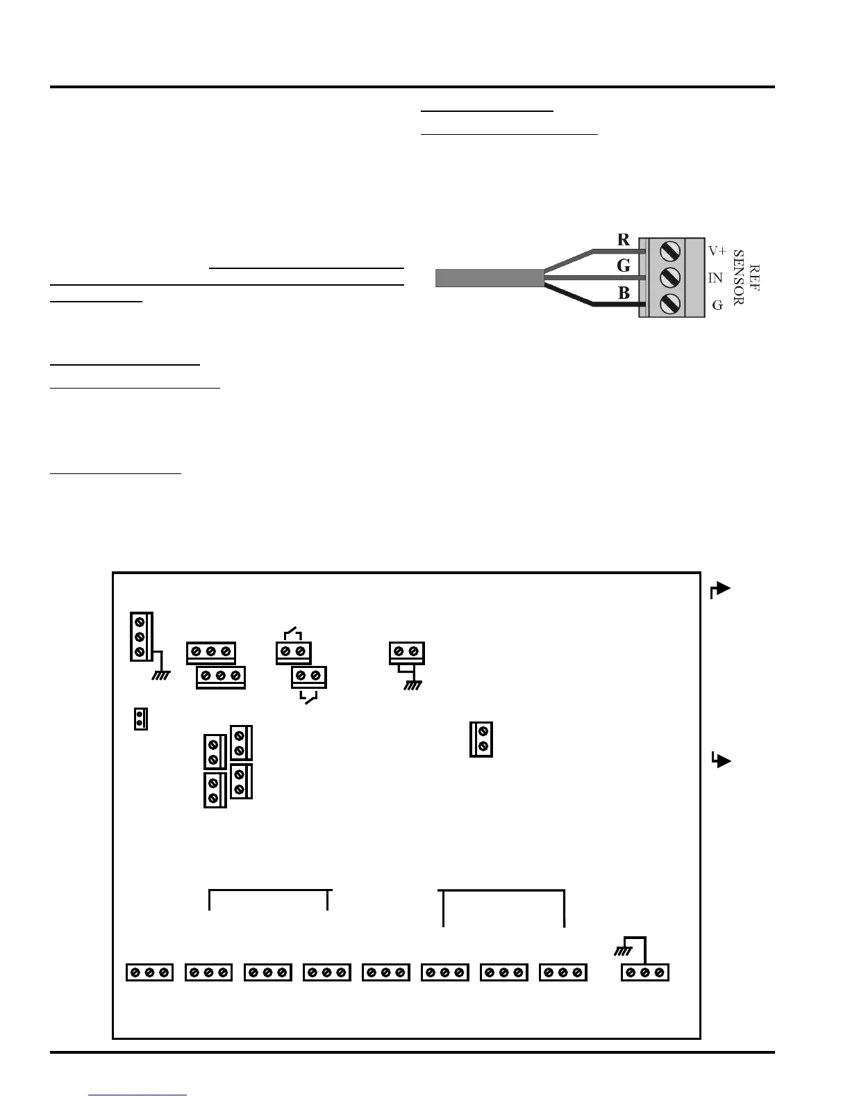
SENSOR WIRING
The sensors will not work if improperly wired and may be
damaged if wired improperly. We suggest using a three-wire
color-coded cable for identification. For consistency, connect
the black wire to GND on the sensor as well as the SHERLOCK
2-Series, the red wire to V+ and the green/white wire to IN (i.e.
match the same color wire with the same input/output identity).
The sensor covers are connected to the housing using either
plastic snap-on connections or screws. Always replace the
cover after maintenance!. Do not run the sensor wire near
power lines or high voltage wiring, otherwise control may
act erratically!!
SENSOR WIRE TECHNICAL SPECIFICATIONS
SOLID STATE SENSOR
For Wiring Runs of 0 to 100 ft
Twisted, Triad (3-wire) - 22 AWG
Belden part number 8443 or 9407 (For shielded applica-
tions - 9363. For Plenum installations - 83395)
For Runs 100 to 1000ft
Shielded, Twisted Triad (3-wire) - 18 AWG
Belden part number 8770 (For Plenum installations -
83335)
INFRARED SENSOR
For Wiring Runs of 0 to 1000 ft
Shielded, Twisted, Triad (3-wire) - 18 AWG
Belden part number 8770 or 9407
Cable wire from other manufacturers with the same specifica-
tions and ratings can also be used.
SHERLOCK 102/202 WIRING
SHERLOCK 102 & 202 WIRING - (Refer to 44-0221 or
44-0295 Infrared Refrigerant Gas Sensor Manuals and
44-0283 Solid-State Sensor Manual for more information
about sensor wiring and configuration.)
Wiring diagram for the Sherlock 102, one sensor control and
Sherlock 202, two sensor control. Remove the 4 screws holding
the faceplate to the housing to access the wiring screw termi-
nals for the sensor at the top of the board and dry contact relays
located on the bottom of the board. Follow the silkscreen direc-
tions also located on the back of the control faceplate.
# 1
NONCC
REFR
LEAK
LEVEL 1
+12V
IN
GND
44-0317D
WARNING: TO AVOIDCONTROL MALFUNCTION,RUNLOWVOLTAGE
WIRES(INPUTS...) AWAY FROMHIGHVOLTAGEWIRES,
USESEPARATECONDUITS.
SHERLOCK 102/202TERMINAL CONNECTIONDIAGRAM
20 21 22 25 26
UN-PLUGABLE
MAINCONNECTOR
+
BUZZER
COMM
REFR
SENSOR A
SETBACK
IN1
SENSORB
+12V
IN GND
CABLESHIELD
WIRECONNECTION
+
-
12VDC
OUT
REPLACEFUSEWITH THESAME TYPE ANDRATINGONLY (5.0 A,250V AC)
12VSTROBE
LIGHT
12VHORN/
STROBE
-
+
-
IN2
4-20mA OUT
# 2 # 3 # 4
NONCC NONCC NONCC
REFR
LEAK
LEVEL1
REFR
LEAK
LEVEL2
REFR
LEAK
LEVEL2
# 5 # 6 # 7 # 8
SNR A
ZONE
SNR A
ZONE
SNRB
ZONE
SNRB
ZONE
NONCC NONCC NONCC NONCC LGN
EARTH
GROUND
P23
100-240VAC
2.5 AMP MAX.
50/60HZ
POWERIN
SILENCE-ABLE
SNR A
SNRB
+
+
+
+
-
-
-
-
4-20mA OUT
(0-1500PPM)
 Loading...