EasyManua.ls Logo

Genie 36664R Series - User Manual

Genie 36664R Series
2 pages
Print Icon
To Next Page IconTo Next Page
Loading...
Printed in the USA
1. Pull Emergency Release Cord on Carriage to disengage Opener to close door if necessary. (If unable to lower door
using Opener, use extreme caution manually closing door. Before pulling Emergency Release Cord, make certain
people and objects are clear of door opening.)
2. Unplug Opener Power Cord from power receptacle.
3. Open Lens Cover by pressing middle tab inward and remove Light Bulbs. FIG. 1. (See reverse side)
4. Remove Wall Control and Safe-T-Beam wires from Terminal Block located on side of Opener FIG. 2. Use small
common screwdriver to press in on orange tabs while gently pulling wires from block. Mark wires to help facili-
tate replacement.
5. Remove Network and Battery Backup Harnesses from front of Opener (if applicable).
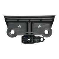
6. Remove the Cotter Pin & Clevis from Door Arm to separate door from Opener. FIG. 3.
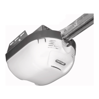
7. Remove Motor Head and Rail Assembly from mounting brackets and set on a clean work surface or oor.
NOTE: Be aware of the Motion Detector Bulb on bottom of Powerhead Cover. Do not set operator weight on this bulb
FIG. 4.
8. Pull emergency Release Cord to disconnect Shuttle from Rail (if not already released)
9. Push Shuttle out of Rail towards the door end of the Rail to remove old Shuttle.
10. Install new Shuttle in reverse order.
11. Reinstall Opener Assembly in reverse order as removed. Reference your Owners Manual and Installation Poster.
12. Install Wall Control and Safe-T-Beam wires. Install Battery Backup and/or Network Harnesses if applicable.
13. Install Light Bulbs and close Lens Cover.
14. Install Clevis & Cotter Pins from Door Arms to Shuttle.
15. Remove Release Cord and Handle from old Shuttle and Install on new Shuttle.
16. Move disconnect lever on Shuttle to the upwards position and operate Door until Shuttle connects with Carriage
inside rail. ese two will lock together.
17. Plug Opener in.
18. Clear and reprogram Limit Controls per Owners Manual.
Shuttle Replacement
36664R
37864500887, 02/01/2011
WARNING
WARNING
BESUREELECTRICALPOWERHASBEENDISCONNECTEDFROMTHEINPUTPOWERLINESPRIORTOREMOVINGTHE
MOTORCOVER.
!
is repair will require removal of the unit from its mounting hardware and repairs made on a bench or oor. Refer to your
Owners Manual and/or Installation Poster for proper assembly and carefully read and understand all warnings and cautions
pertaining to your unit.
ANYANDALLREPAIRSMADETOTHISUNITMUSTBEPERFORMEDWITHTHEDOORDISCONNECTEDFROMTHE
OPENERANDINTHECLOSEDPOSITION.
!
Question and Answer IconNeed help?

Do you have a question about the Genie 36664R Series and is the answer not in the manual?

Summary

Shuttle Replacement Guide

Critical Safety Warnings

Essential safety precautions and warnings to be followed before and during the shuttle replacement procedure.

Shuttle Replacement Procedure

Step-by-step instructions for the removal of the old shuttle and installation of the new shuttle.

Overview

This document outlines the procedure for replacing the shuttle component of a garage door opener, a repair that requires the unit to be removed from its mounting hardware and serviced on a bench or floor. It emphasizes the importance of consulting the owner's manual and installation poster for proper assembly and understanding all warnings and cautions.

Safety Warnings:

  • Electrical Disconnection: Before removing the motor cover, ensure that electrical power to the unit has been disconnected from the input power lines.
  • Door Position: All repairs must be performed with the door disconnected from the opener and in the closed position.

Shuttle Replacement Procedure:

The replacement process begins with a series of preparatory steps to safely access the shuttle mechanism:

  1. Disengage Opener: Pull the Emergency Release Cord on the Carriage to disengage the opener. If the door does not close automatically, extreme caution must be exercised when manually closing it. Ensure no people or objects are in the path of the door opening before pulling the release cord.
  2. Unplug Power: Disconnect the opener's power cord from its electrical receptacle.
  3. Remove Light Bulbs: Open the Lens Cover by pressing the middle tab inward, then remove the light bulbs (refer to FIG. 1 on the reverse side of the document).
  4. Disconnect Wires: Remove the Wall Control and Safe-T-Beam wires from the Terminal Block located on the side of the opener (refer to FIG. 2). Use a small common screwdriver to press inward on the orange tabs while gently pulling the wires. Mark the wires to facilitate correct reinstallation.
  5. Remove Harnesses: Disconnect the Network and Battery Backup Harnesses from the front of the opener, if applicable.
  6. Separate Door Arm: Remove the Cotter Pin and Clevis from the Door Arm to detach the door from the opener (refer to FIG. 3).
  7. Remove Motor Head and Rail Assembly: Unmount the Motor Head and Rail Assembly from its mounting brackets. Place the entire assembly on a clean work surface or floor. A crucial note here is to be mindful of the Motion Detector Bulb on the bottom of the Powerhead Cover; avoid placing the operator's weight on this bulb (refer to FIG. 4).

Once the preliminary steps are complete, the actual shuttle replacement can proceed:

  1. Disconnect Shuttle: Pull the emergency Release Cord to disconnect the Shuttle from the Rail, if it is not already released.
  2. Remove Old Shuttle: Push the old Shuttle out of the Rail towards the door end to remove it completely.
  3. Install New Shuttle: Install the new Shuttle by reversing the removal process.
  4. Reinstall Opener Assembly: Reinstall the opener assembly in the reverse order of removal. Refer to your owner's manual and installation poster for guidance.
  5. Reconnect Wires: Reinstall the Wall Control and Safe-T-Beam wires. Install Battery Backup and/or Network Harnesses if applicable.
  6. Reinstall Light Bulbs: Install the light bulbs and close the Lens Cover.
  7. Reconnect Door Arm: Install the Clevis and Cotter Pins from the Door Arms to the Shuttle.
  8. Transfer Release Cord: Remove the Release Cord and Handle from the old Shuttle and install them on the new Shuttle.
  9. Reconnect Shuttle to Carriage: Move the disconnect lever on the Shuttle to the upwards position. Operate the door until the Shuttle connects with the Carriage inside the rail, ensuring they lock together.
  10. Plug In Opener: Plug the opener back into the power receptacle.
  11. Reprogram Limits: Clear and reprogram the Limit Controls according to the instructions in your owner's manual.

This detailed guide ensures a systematic and safe approach to replacing the shuttle component, restoring the proper function of the garage door opener.

Genie 36664R Series Specifications

General IconGeneral
TypeChain Drive
Horsepower1/2 HP
Battery BackupNo
Max Door Height7 ft
Drive SystemChain
Remote ControlYes
Voltage120V
Speed7 inches per second

Related product manuals