Do you have a question about the Genie GS-3246 and is the answer not in the manual?
Details essential safety rules and necessary skills for maintenance.
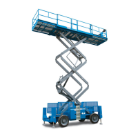
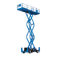
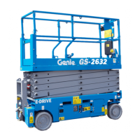
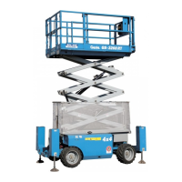
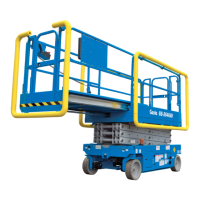
Lists service manuals by model and serial number range.
Explains the structure and meaning of equipment serial numbers.
Outlines critical safety rules and conditions for performing maintenance.
Details personal safety precautions and safe work area procedures.
Details battery, fluid capacities, and tire/wheel specs.
Covers drive speed, braking distance, gradeability, and noise levels.
Details hydraulic oil, components, system pressures, and filters.
Lists plug torque and valve coil resistance values.
Provides torque values for JIC and SAE hydraulic connections.
Explains the step-by-step process for torquing JIC fittings.
General rules and explanation of symbols used in maintenance.
Outlines inspection types, frequencies, and reporting requirements.
Covers manual/decal inspection, pre-operation checks, and function tests.
Details inspection of batteries, electrical systems, tires, brakes, and drive speeds.
Covers platform overload system testing and breather cap replacement.
Details scissor arm wear pad checks and hydraulic tank filter replacement.
Outlines hydraulic oil testing or replacement procedures.
Safety and preparation rules before starting repairs.
Covers circuit boards, controller adjustments, and software configuration.
Provides diagrams and disassembly procedures for scissor assemblies.
Details procedures for removing and servicing the lift cylinder.
Explains calibration procedures for the overload system.
Covers procedures for testing and removing the hydraulic pump.
Details components and adjustments for various manifolds and valves.
Covers yoke, drive motor, steer cylinder, and bellcrank removal.
Describes procedures for removing the drive brake.
Details procedures for removing and servicing outrigger cylinders.
Safety and preparation rules for troubleshooting.
Explains the purpose of the fault code section.
Explains diagnostic codes and a specific troubleshooting tip.
Lists fault codes, problems, causes, and solutions for general system faults.
Describes outrigger control pad indicator lights.
Lists specific fault codes related to the outrigger system.
Safety rules and legends for understanding schematics.
Introduces electrical schematics and their organization.
Introduces hydraulic schematics and their organization.
Lists and describes electrical components and wire color coding.
Details ECM and Outrigger ECM connector pin assignments.
Provides diagrams for ground controls, sensors, platform, and outrigger controls.
Identifies limit switch locations on the machine.
Explains standard electrical symbols used in schematics.
Provides specific electrical diagrams based on machine configuration.
Provides specific hydraulic diagrams based on machine configuration.
| Drive Speed - Raised | 0.5 mph |
|---|---|
| Gradeability | 25% |
| Platform Height | 32 ft |
| Lift Capacity | 700 lbs |
| Machine Length | 8 ft (2.44 m) |
| Drive Speed - Stowed | 3.5 km/h |
| Drive Speed | 2.2 mph (3.5 km/h) |
| Power Source | 24 V DC (Four 6 V batteries) |
| Machine Width | 46 in |