LYNX 07 24V
ENGLISH
Guide for the installer
Page 17
1. GENERAL CHARACTERISTICS
Thank you for choosing our product. GENIUS is sure you will get the performances you expect to satisfy your requirements. All
our products are the result of a many years’ experience in the field of the automated systems, strengthened by being part of
a world leading group in this sector.
The LYNX 07 control unit was developed and realized to control electro-mechanical barriers for vehicle access control.
Thanks to the innovative switching supply system, the control unit is able to automatically adapt to different input voltages
(230 Vac o 115 Vac) keeping unchanged the outputs value on both the motor and the accessories, without suffering any
variations.
The very simple programming of the main functions enables reduced installation times, while a series of built-in LEDs provides
for a rapid and safe diagnostics on the status of safety devices and control devices connected to the control unit.
Thanks to the encoder management, this control unit, if correctly installed and adjusted, enables you to reduce the number
of devices necessary for the realization of an installation in compliance with current safety standards.
To ensure people’s safety, all warning and instructions in this booklet must be carefully obser ved.
Incorrect installation or incorrect use of the product could cause serious harm to people.
Carefully read this manual before installing the product.
Store these instructions for future references.
2. TECHNICAL SPECIFICATIONS
Power supply voltage and frequency 230 Vac 50 Hz / 115 Vac 60 Hz
Absorbed power 5 W
Max. power at thrust 280 W
Accessories max. load 500 mA
Operating ambient temperature -20°C +55°C
Protective fuses 2 fuses, replaceable + 4 fuses, self-resetting
Function logics
Automatic (A) / Step-by-step automatic (AP) / Manual (E) / Step-by-step
manual (EP) / Condo (D)
Opening/Closing max. time 60 seconds
Pause time Adjustable on 7 levels of 5 seconds up to 4 minutes
Encoder sensitivity Adjustable on four levels
Terminal board inputs
Mains power supply (230/115 Vac) / FCA and FCC travel limits/ Photocells /
Stop/ Open-Close / Open / Close / Safety dev. test / Battery
Rapid connector 3-pin molex coupling for encoder / 3-pin input for receiving module
Terminal board outputs
Motor power supply 24Vdc / Flashing lamp 24Vdc / Indicator light 24Vdc max.
5W / Rod lights 24Vdc / Power supply to accessories / Battery charger
Board dimensions 168mm x 146mm
3. PREPARATIONS
Make sure that an adequate differential switch is installed upstream of the system as specified by current safety standards.
On the power supply mains install a thermal breaker with omnipolar switching.
Make sure that an adequate earthing system is available.
To lay cables, use adequate rigid and/or flexible tubes.
Always separate the 230/115 Vac power cables from low voltage connections, using separate sheaths to avoid possible
interference.
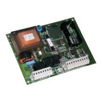
4. BOARD LAYOUT
With reference to figure 1:
Pos. Description Pos. Description
CN1 Power supply terminal board OP OPEN input radio programming push-button
CN2 Motor and travel-limit terminal board O/C OPEN/CLOSE input radio programming push-button
CN3 Light outputs terminal board FCA FCA input signalling LED
CN4 Inputs terminal board FCC FCC input signalling LED
CN5 Battery terminal board FSW SAFETY DEVICES input signalling LED
JP1 Not used STOP STOP input signalling LED
JP2 Radio module rapid coupling OP/CL OPEN/CLOSE input signalling LED
JP3 Encoder connection Molex OPEN OPEN input signalling LED
F1 Power supply 230/115Vac circuit fuse CLOSE CLOSE input signalling LED
F5 Motor power supply circuit fuse DL6 OPEN/CLOSE radio input signalling LED
•
•
•
•
•
 Loading...