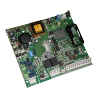
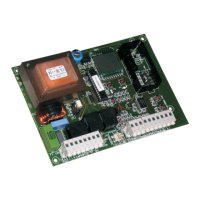
7. CONTROL LEDs
There are 9 control LEDs on the control unit displaying the input status continuously. The meaning of the LEDs is shown on the
table below.
LED ON OFF
FCA - Opening travel limit FCA Travel limit not engaged Travel limit engaged
FCC - Closing travel limit FCC Travel limit not engaged Travel limit engaged
FSW - Photocells input Safety devices not engaged Safety devices engaged
STOP - STOP command input Command not active Command active
OP/CL - Open/Close command input Command active Command not active
OPEN - Open command input Command active Command not active
CLOSE - Close command input Command active Command not active
DL6 - Open/Close command radio input Radio input active Radio input not active
DL7 - Open command radio input Radio input active Radio input not active
The bold print indicates the condition of the LEDs with the automated system closed at rest.
The STOP LED must always be ON; it turns off when the command is activated.
If safety devices are not connected, make a connection between terminals 17 & 22. FSW LED must always be ON; it turns
off when the safety devices are engaged.
8. OPERATION OF THE DISPLAY
The control unit has a back-lit large display enabling you to view and program the operating parameters of the automated
system. Furthermore, it always shows the status of the automated system during normal operation. The following table shows
all indications on the display during normal operation:
Displayed value Status of the automated system / description
- -
Automated system closed at rest
O P
Automated system opening or open
t c
Automated system open in pause (only with the selected automatic re-closure)
C L
Automated system closing
A S
Service request: it is shown only if the function was enabled, see paragraph 9 and if the
number of set cycles has been reached.
p r
Control unit in work cycle learning phase
9. OPERATING PARAMETERS
The operating parameters and their programming are shown on the display of the control unit with two characters: a letter, lower
case or upper case, and a number. The letter indicates the operation of the operating parameter you are modifying, whereas
the number indicates the set value. For example, if you read “
b2
” on the display, this means you are modifying parameter “
b
”,
motor power and obstacle detection sensitivity, and that it is currently set on “
2
”.
To access the programming phase of the operating parameters, at first start-up, observe the following procedure:
Power up the system and check that all LEDs in the control unit are in the situation indicated in paragraph 7.
Make sure that the display shows value “
- -
“, automated system at rest.
Press and hold down push-button P1 until the name of the first parameter appears on the display with the relevant
value.
Press push-button P2 to modify the set value.
To move on the next parameter, press push-button P1.
When 60 seconds have elapsed without any push-button being pressed, the control unit automatically exits the adjustment
mode and any modifications are memory stored. You can manually exit the adjustment phase by scrolling all the
parameters with push-button P1. When the display shows value “
- -
” you have returned to normal operation.
The following table summarises all settable operating parameters and the assignable values:
1.
2.
3.
4.
5.
6.