8
ENGLISH
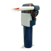
SIMPLE AUTOMATED SYSTEM
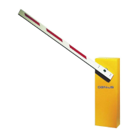
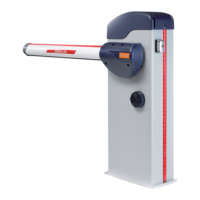
The SIMPLE automated system is an electronic barrier designed
for vehicle accesses
The automated system mainly consists of three parts:
A motor body which integrates the non-reversing low voltage
motor, the control board, the flashing light, the balancing spring
and the release system.
The rod of which several types are available according to instal-
lation requirements.
The securing support, available for on-wall or on-column instal-
lation.
The built-in control unit was positioned to facilitate all the wiring,
programming and adjustment operations.
A handy manual release, protected by a personalised key, makes it
possible to move the rod manually in the event of a power cut.
Before you begin to install the barrier, read all the instructions
carefully. Incorrect installation or incorrect use of the au-
tomated system could be a source of danger to people.
The automated system was designed and built for vehicle
access only - do not use for any other purpose.
Anything not expressly specified in these instructions is not
permitted.
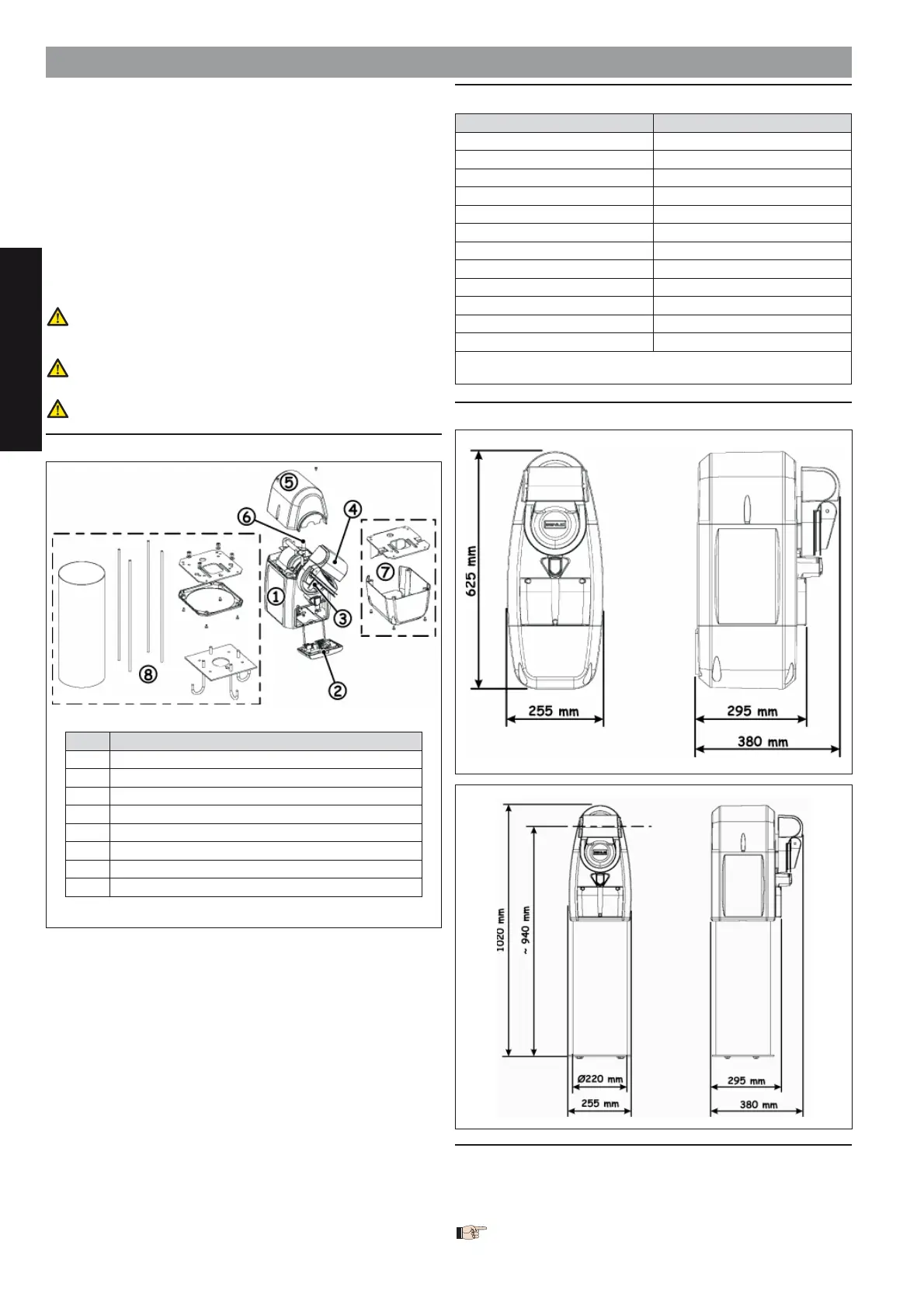
1. DESCRIPTION OF COMPONENTS
•
•
•
2. TECHNICAL SPECIFICATIONS
MODEL SIMPLE
Power supply 230/115 Vac 50/60Hz
Motor power supply 24 Vdc
Absorbed power 80 W
Absorbed current 0.35 A
Max. torque. 130 Nm
Opening time 3 sec
(1)
Max beam length 4 m
Max consecutive cycles 100
Operating ambient temperature
-20 ÷ +55°C
Motor body weight 20 Kg
Protection class IP 44
Dimensions See fig. 2
(1)
The indicated opening time refers to a correct installation
without any slow downs
3. DIMENSIONS
4. ELECTRIC PREPARATIONS (standard system)
Fig.4 shows an installation with column support. The electrical ca-
bles to be prepared are the same as those for on-wall installation;
for the position of the cables, refer to paragraph 4.3.
To lay cables, use adequate rigid or flexible tubes.
Fig. 1Fig. 1
Pos. Description
햲
Motor body
햳
Control unit
햴
Release device
햵
Rod carrying pocket
햶
Covering housing
햷
Flashing light
햸
Wall mounting kit (not supplied)
햹
Column kit (not supplied)
Pos. Description
햲
Motor body
햳
Control unit
햴
Release device
햵
Rod carrying pocket
햶
Covering housing
햷
Flashing light
햸
Wall mounting kit (not supplied)
햹
Column kit (not supplied)
Fig. 2Fig. 2
Fig. 3
Fig. 3