Do you have a question about the Genius SW-2.1 355 and is the answer not in the manual?
Lists crucial safety measures for handling speakers to prevent damage or injury.
Details causes and solutions for a system that does not power on or show an indicator light.
Provides steps to diagnose and fix issues where no audio output is produced.
Addresses problems specifically affecting the right audio channel output.
Addresses problems specifically affecting the left audio channel output.
Presents the complete circuit diagram for the speaker system for detailed technical analysis.
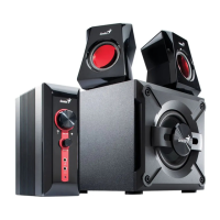
This document serves as a comprehensive Service Guide for a speaker system manufactured by Key System Corp, identified by the model number SW-2.1 355. It is designed to assist technicians and service personnel in understanding, troubleshooting, and maintaining the device effectively. The guide is structured to provide a logical flow of information, starting from general handling procedures to detailed repair instructions and part lists.
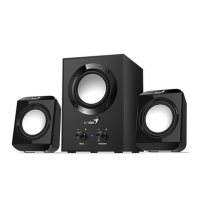
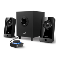
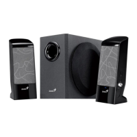
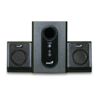
The primary function of this device is to provide audio output, likely as a 2.1 channel speaker system, comprising a subwoofer and two satellite speakers. The guide implies its use with various audio sources such as DVD, CD, TV, and MP3 players, indicating its versatility as a general-purpose audio output system for entertainment or personal computing. The block diagram illustrates the signal flow, showing inputs from various sources, processing through master volume and woofer volume controls, and amplification for both satellite and subwoofer outputs. This suggests a user-friendly interface for adjusting overall sound levels and bass intensity.
From a usage perspective, the system is designed for straightforward operation, connecting to audio sources and providing amplified sound. The presence of a master volume and a dedicated woofer volume control allows users to customize their listening experience, adjusting the overall loudness and the emphasis on low-frequency sounds. The LED indicator serves as a visual cue for the device's power status, which is a common and helpful feature for users to quickly ascertain if the system is powered on. The guide also implicitly highlights the importance of proper placement, suggesting that the speakers should be on a flat, stable surface and away from environments with mist, smoke, excessive dust, or corrosive elements to ensure optimal performance and longevity.
Maintenance features are a core component of this service guide, providing detailed instructions for diagnosing and rectifying common issues. The "How to Handle Defective Returns" chapter outlines a systematic approach for receiving, verifying, analyzing, and repairing defective units. This includes a flowchart that guides technicians through the process, from initial problem verification to identifying malfunction causes, deciding on rectification methods, replacing defective parts, and finally, re-verifying and returning the repaired speakers to customers. This structured approach ensures efficiency and accuracy in the repair process.
The guide addresses several common problems, each with a dedicated troubleshooting flow. For instance, "No power, LED unlighted" directs technicians to check the transformer, AC cable, power switch, and soldering connections. This indicates that power supply issues are a frequent point of failure and require careful inspection of these components. Similarly, "No sound" troubleshooting involves checking the input cable, the 8P assembled line connection between CON1 and CON2, defective components like VR1, JK1, U1, U2, and potential PCB damage. This multi-faceted approach ensures that various potential causes for a lack of sound are systematically investigated.
Specific sound issues are also covered, such as "Right channel no sound" and "Left channel no sound." These sections guide technicians to inspect the input cable, speaker cable, PCB, and specific components like JK1, JK2, CON1, CON2, resistors (R8, R1, R7, R2, R19, R20), capacitors (C1, C3, C10, C2, C4, C11), and integrated circuits (U1, VR1). The detailed component references are crucial for precise diagnosis and repair, allowing technicians to pinpoint the exact faulty part.
"Woofer no sound" troubleshooting focuses on the assembled line between CON1 and CON2, specific resistors (R9, R10, R14, R15), capacitors (C15, C18, C20, C21), CON4, and ICs (U2, U3) or surrounding components. This highlights the distinct circuitry involved in the subwoofer's operation and the need for specialized checks for bass output issues.
The "Noise" section addresses unwanted audio artifacts, directing technicians to examine diodes (D1-D4), capacitor C29, ICs (U1, U2, U3), and their surrounding components for dry-soldering or defects. It also considers vibration from long lead wires of driver units and general driver unit damage. This comprehensive approach to noise issues covers both electrical and mechanical causes.
Finally, "LED indicators no light" focuses on the LED itself, resistor R18, and the PCB for defects, dry-soldering, or breakage. This ensures that even minor cosmetic or indicator issues can be resolved.
The "Part list" chapter is an essential maintenance feature, providing a detailed breakdown of all components for both the subwoofer and satellite speakers, along with their respective part numbers. This list is critical for ordering replacement parts and ensuring that repairs are performed with the correct components. The inclusion of specific part numbers like EP40711156 for the knob, EP13F00319 for the transformer, and EPIC020001 for the ICs demonstrates a high level of detail, facilitating accurate inventory management and procurement for service centers.
"Important Notes" further emphasizes best practices for maintenance. The section on "Packing requirement for sending the PCB assembly by post" underscores the delicate nature of electronic circuit boards, advising on the use of static protecting bags and reliable external packing to prevent damage during transit. This highlights the company's awareness of potential issues during the repair logistics process and provides guidance to mitigate risks. The note on "Short of spare parts while repairing a speaker system" offers a practical solution for resource management in service centers, suggesting that parts can be cannibalized from other defective units if new spares are unavailable, to maximize the number of functional systems. This pragmatic advice is valuable for maintaining efficiency in repair operations.
In summary, this service guide provides a robust framework for the maintenance and repair of the SW-2.1 355 speaker system. It combines systematic troubleshooting, detailed component identification, and practical advice on handling and logistics, ensuring that service personnel can effectively diagnose, repair, and return the device to optimal working condition. The emphasis on safety precautions and proper handling throughout the document further reinforces a commitment to quality service and product longevity.
| Speaker Type | 2.1 |
|---|---|
| Signal-to-Noise Ratio | 70 dB |
| Volume Control | Yes |
| Input Sensitivity | 450mV |
| Total Power Output | 10 W |
| Frequency Response | 20Hz - 20kHz |
| Input | 3.5mm stereo |
| Input Impedance | 10k ohms |
| Controls | Volume |
| Power Supply | AC |
| Driver Unit | Subwoofer: 4"; Satellite: 2.5" |