1-3
Introduction to GR228X Test Systems
Component Description
Test Instruments The source and measure instruments perform a variety of device tests. For example,
by forcing a known voltage from the dc source and measuring the current, the
software computes the value of dc resistance under test using Ohm’s Law (R=E/I).
Test Fixture
Receiver and
Support Circuitry
Provides an interface between the test instruments and the variety of boards that
undergo tests. Fixtures, which are uniquely fabricated for each board design to be
tested, are mounted to the test system’s receiver. Through the fixture, the test
system establishes electrical connections between the test instruments and
individual components on the UUT.
Basic System Components
The GR228X systems include a variety of specially designed interconnected modules and
components that provide easy access at the front for UUT testing and at the rear for equipment
servicing. Internal ventilation is provided by positive pressure air circulation from air intakes on
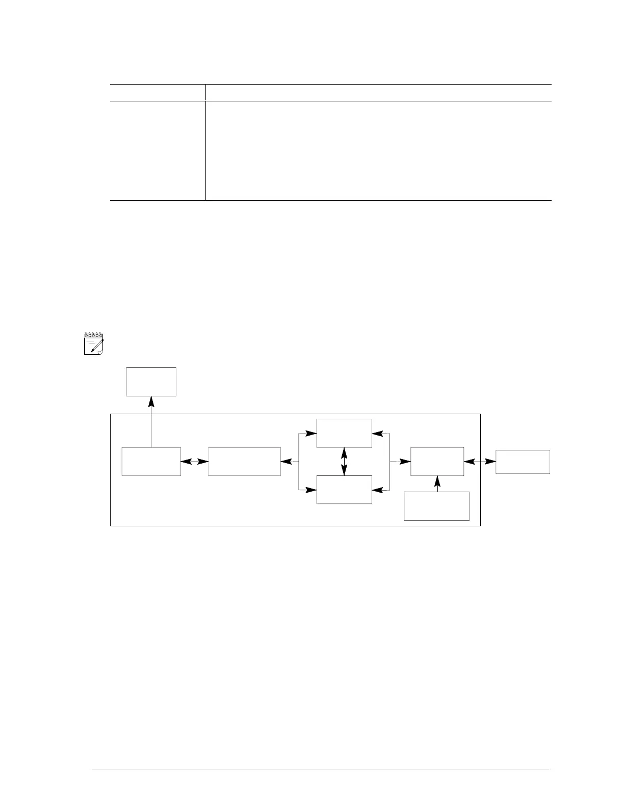
each cabinet. Figure 1–2 shows the system as a block diagram. The basic system contains a PC,
analog and digital subsystems, a receiver, and UUT power supplies.
NOTE The GR2281A and GR2287A Test Systems do not contain a digital subsystem.
(MTG) INTERFACE
PERSONAL
STRIP
MXI-TO-GENRAD
ANALOG
SUBSYSTEM
DIGITAL
SUBSYSTEM
RECEIVER
UUT POWER
SUPPLIES
UNIT UNDER
TEST
PRINTER
42541.1
COMPUTER
GR228X Test System
Figure 1–2 Basic System Block Diagram