REPLACEMENT PROCEDURE 2:
RETENTION ASSEMBLY
1. Squeeze the sides of the TPL together and remove it from the helmet.
2. Remove the earcups from the retention assembly as in Replacement
Procedure 3, Steps 1-3 (Page 16).
3. Remove the energy-absorbing liner as follows as in Replacement
Procedure 1, Steps 3 and 4 (Page 14).
NOTES
• Prior to removing attaching hardware from retention straps, note which
strap holes are used for attachment. These same holes must be used
when installing new retention assembly.
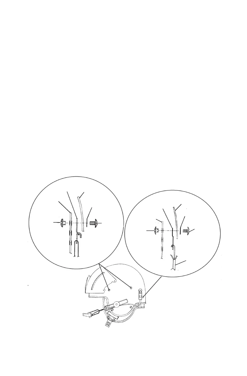
• The front and center straps on both sides share attaching hardware with a
helmet shell cross strap. The left rear strap shares hardware with the
communications cord strain relief plate. When removing hardware from
any of these points, note position and order of attachment to ensure
correct installation (see Figure 14).
4. Remove the six screws (three each side), washers, and posts attaching the
retention assembly to the helmet shell and remove the retention assembly
from the helmet.
15
Figure 14. Retention Assembly Attachment
CROSS
STRAP
RETENTION
STRAP
POST
HELMET
SHELL (REF.)
WASHER
SCREW
HELMET
SHELL (REF.)
WASHER
SCREW
COMM.
CORD
RETENTION
STRAP
POST
STRAIN
RELIEF
(Continued on next page)