REPLACEMENT PROCEDURE 6:
DUAL VISOR ASSEMBLY
1. Remove the four screws (two on each side) attaching the existing visor
assembly to helmet shell.
NOTES
• Be sure to install the spacers and tracks on the side of the housing (right
or left) for which they were configured. When installed correctly, these
parts will curve toward the center of the visor housing (see Figure 20.)
• Most visor assemblies include nut plates to be installed between the posts
and the underside of the helmet shell to hold the posts in place. (Visor
assemblies manufactured before 1992 may not have nut plates.) Steps 5
and 6 on the next page describe the installation of the nut plate. The flat
side of the nut plate (the side without the prongs) must be installed facing
the visor housing. Either edge of the nut plate — the straight edge or the
slotted edge — may face outward; in Figure 20, the straight edge is
shown facing outward.
• Spacer, tracks, screws, posts, and nut plate are shown only on the left
side of the visor housing in Figure 20. A similar configuration exists for
the right side.
• Before installing screws, apply Weldwood glue #281 or equivalent to the
first two threads of each screw.
21
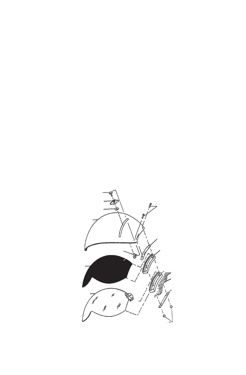
Figure 20. Dual Visor Assembly (Exploded View)
CENTER SCREW
OUTER VISOR LOCK
WASHER
HOUSING
OUTER
VISOR KEY
OUTER VISOR
INNER VISOR
HOUSING SCREWS
(TWO ON EACH SIDE)
DETENT SPACER
(ONE ON EACH SIDE)
UPPER TRACK
(ONE ON EACH SIDE)
LOWER TRACK
(ONE ON EACH SIDE)
NUT PLATE
(ONE ON EACH SIDE)
POSTS (TWO ON EACH SIDE)
HELMET SHELL
(Continued on next page)