4 Assembly and setting into operation
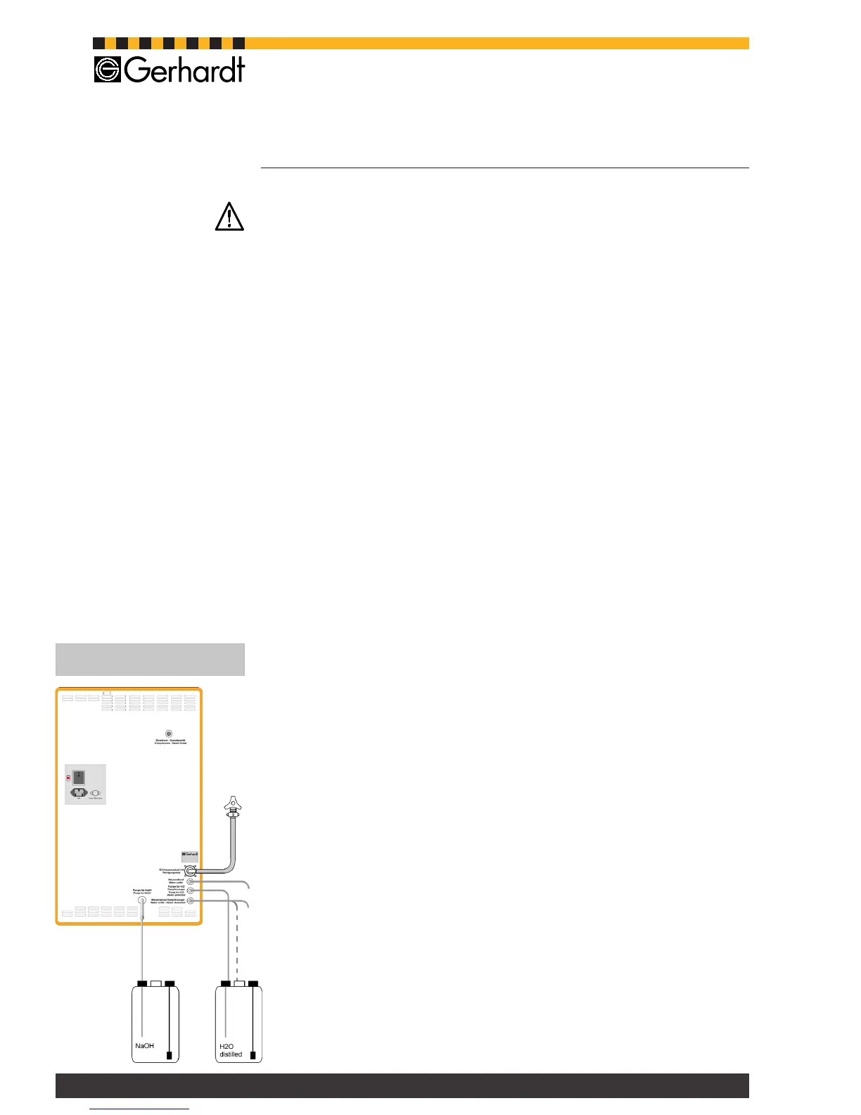
Fig. 4.1.
Tubing connections
4.1. General
Please observe the local water and waste regulations and those of your public
water supply company!!
Please note that the length of the inlet and outlet tubing is restricted to 2 metres.
Theapplianceshouldbelocatedonaxedlaboratorybench,closetothecold
water connection and a drain.
Thereshouldbesufcientspaceforthesetoftanksbelowtheworkbench.
Connect the water inlet tubing to a dedicated cold water tap.
The water pressure must be at least 0,5 bar in order to operate the integrated
pressure controller.
The Vapodest 10 comes completely preassembled. Please unpack the instrument
with care!
1. Place instrument on work bench.
2. Unpack accessories.
3. Placesetoftanksfordistilledwaterandsodiumhydroxidebelowthebench.
Make sure that the set of tanks are not placed any higher than the distillation unit!
4.2. Tubing connections
When connecting the tubings please observe the inscription on the connection
pipes at the back of the equipment
- ConnectinlettubingforNaOH(PVC-tubing4/7)tocorrespondingpipeatthe
rear of the equipment and link it to the NaOH tank.
- Connect cooling water inlet tubing (pressure proof tissue tubing 10/17) to
cooling water inlet and laboratory water supply.
- Connectcoolingwateroutlettubing(PVC-tubing8/12)tocorrespondingpipe
at the rear of the equipment and place in the drain.
- Slide inlet tubing for H
2
Osteamgenerator(PVCtube8/12)ontheconnection
at the rear of the instrument and link it to the distilled water tank.
- Connectwateroutlettubingforsteamgenerator(PVC-tubing8/12)tocorre-
sponding pipe at the rear of the equipment and link it to the drain or to the
distilled water tank for recycling.