Grid: Velocity Profile Test Grid 6" from back and sides,
6 3/4" from front
LFGI 3 & 4, 5 5/8" apart left to right, 6" apart front to back
LFGI 6, 6" apart left to right, 6" apart front to back
Note: Above grid measurements made on work tray correspond to proper location at 12”
below diffuser.
The LFGI USP should maintain ISO Class 5 conditions in the work environment regardless
of pressurization. To verify, divide the work tray into 1 square foot areas and sample the
center of each zone for a minimum of 1 minute per zone.
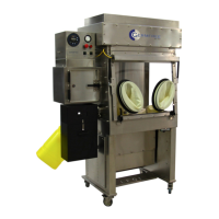
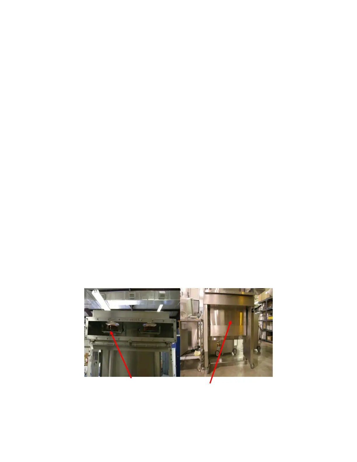
The unit has two main HEPA filters, one above the work zone (supply) and one below
(exhaust), see figure 1. The Supply HEPA filter should be scanned with a Photometer while
challenged with DOP or equivalent. The aerosol challenge can be introduced to the
upstream side of the HEPA filter through the supply blower inlet. An upstream challenge
can be read through the port opposite the LFGI control panel by removing the hex head
plug. If access to the side of the unit is not possible, the upstream challenge can be read
through the port inside the control panel connected to the “supply HEPA filter” pressure
gauge. For the exhaust HEPA filter the challenge is introduced into the work area and a
mass flow reading should be measured in the air recycle plenum on the back top of the unit.
All HEPA filters are 99.99%.
Fig.1 Supply filter access (left) and Exhaust filter access (right)
62
 Loading...