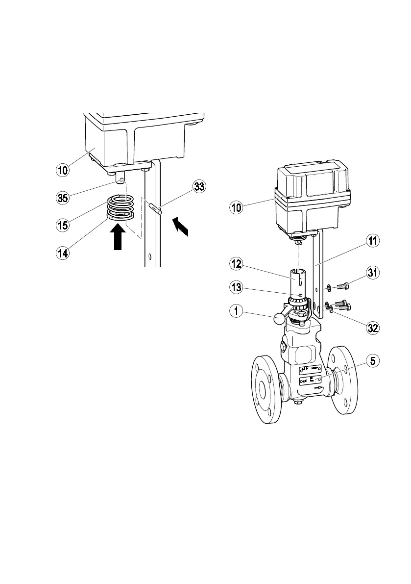
Install the actuator as follows:
Insert the spring (15) and thrust ring (14) in the
actuator (10).
Using a hammer, knock the grooved pin (33)
into the hole (35) in the drive shaft.
Position the coupling (12) on the control lever
(1).
Fit the bracket (11) onto the body.
Screw the bracket onto the body using three hex
bolts (31) and the shims (32).
Adjust the control lever until the coupling
engages.
Make sure the coupling is lying flat on the
control lever.
Tighten the three hex bolts (31) to a torque of
30 Nm.
Adjust the actuator (10) as described in the
actuator installation & operating manual.
You must set the switch cams for "OPEN",
"CLOSED" and "OPERATING POSITION". You will
also need to adjust the feedback potentiometer, if
present.
Make sure the "CLOSED" switch cam is
adjusted in the actuator in such a way that the
control pin (13) is nearly touching the right-hand
side of the inspection hole.
In this position, the torque for closing the valve with
the actuator is 10 Nm.
Remove the ATEX label (5) from the body.