B300 Vehicle Docking Reference Guide
1
Installing the Pedestal & Vehicle Docking / Wiring Instructions
2
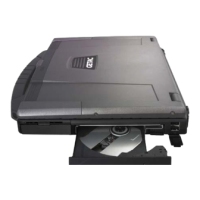
Connecting the
Computer
3
Troubleshooting and
Helpful Tips
CAUTION: This vehicle docking has a built-in power
supply and is designed to be used with an 11~28-volt DC
system only. The voltage output is factory set at 19-volts.
1. Have a qualified technician install the pedestal
to your vehicle. You are highly recommended
to use the Gamber Johnson pedestal as it has
been tested to be compatible to your vehicle
docking.
2. Install the four nuts to fix vehicle docking to
pedestal by inserting the big flat washer first,
then the small washer, and tighten using the nut.
3. Attach BLACK ground wire to the location
where the vehicle battery grounds to vehicle
chassis.
Standard Installation (power switch is
operational) – connect the RED wire to the
supply voltage (V+) from the vehicle. (The
BLUE wire remains unconnected)
By-Pass Installation (power switch is
by-passed) – Connect the BLUE wire to the
supply voltage (V+) from the vehicle. (The
RED wire remains unconnected)
Important Reminders:
z Use only SAE J1128 Type GPT number 14
AWG stranded wire (minimum) to attach the
vehicle docking to the vehicle’s electrical
system.
z Connect lead wires to the disconnect pigtail
using the butt splice connectors provided with
the vehicle docking.
CAUTION: The butt splice connections must be made as
close to the vehicle docking as possible using the
disconnect pigtail provided with the vehicle docking. The
disconnect must be easily accessible. When assembling
the butt splice connectors use only Panduit crimp tools
CT-100, CT-600, CT-1525, CT-1550 or CT-1551.
z Using the wire joint provided with the vehicle
docking, cap the un-used RED or BLUE wire on
the disconnect pigtail.
CAUTION: Use only Panduit crimp tool CT-1550 or
CT-1551.
z Route the lead wires to the battery. Total wire in
the circuit must not exceed 30 feet and must
conform to SAE standard J1128.
z Protect the lead wires from abrasion and chafing
by using wire loom or conduit, and route away
from moving parts or areas where high
temperatures may occur.
z Connection of the supply voltage (V+) must be
kept as close to the battery as possible.
z The power connection must be made with the 10
amp in-line fuse and fuse holder provided with
the dock. Connect the fuse holder to the lead
wire using the butt splice connectors provided
with the fuse holder.
CAUTION: When assembling the butt splice connectors
use only Panduit crimp tools CT-100, CT-600, CT-1525 or
CT-1551.
z The fuse holder location must be kept within 10
inches of the connection to the battery positive,
away from moving parts, and temperatures that
exceed 180
O
F.
CAUTION: If the fuse holder requires replacement it should
be replaced by qualified service personnel using Littelfuse
part number FHM1 (Gamber-Johnson part number 11689).
This device conforms to ASTM standard D471 and SAE
standard J1128.
z Fuse must be inserted in supplied fuse holder.
CAUTION: For continued protection against risk of fire
replace only with the same type and rating of supplied fuse.
The provided fuse is UL Listed, rated at 10 amp, 32 volt
AC/DC fast acting.
z If a timing device is used follow the instructions
of the manufacturer of that device. It must be
wired in-line with the supply voltage (V+) to the
vehicle docking.
1. Make sure that the computer is turned off and
disconnect all cables from the computer.
2.
Slide open the expansion bus connector cover
on the computer.
3.
Push the expansion bus connector latch all the
way inward. This ensures that the expansion bus
connector is all the way inside the enclosure.
4. Align the center notch of computer with front
retainer tab (n) and gently insert the rear side
of the computer into vehicle docking (o).
5. Pull the expansion bus connector latch all the
way outward (n) and at the same time use the
included key to lock the latch (o) in order to
secure the computer to the vehicle docking.
Reverse the previous steps to remove the computer
from the vehicle docking.
Power switch red LED does not light up:
If after applying power to the vehicle docking and
turning the power switch on, the red LED does not
light up – check to see if the BLACK and RED (or
BLUE in by-pass installation) wires are providing
power to the vehicle docking.
If NO – determine the cause and solve.
If YES – the problem is inside the vehicle docking
and should not be adjusted by the installer. Obtain
GETAC customer support
by accessing the web link
at http://www.getac.com Æ Service
.
Helpful Tips (DO):
z If computer malfunctions while vehicle docking
is connected, turn off the computer, disconnect
vehicle docking (see previous section), connect
the AC adapter to the computer, and check to
see if the computer operates normally. If the
computer operates normally, the vehicle docking
may be malfunctioning.
z Remove the computer from the vehicle docking
if any of the following malfunctions occur:
– the vehicle docking is damaged
– a foreign object is inside the vehicle docking
– smoke is emitted
– an unusual smell is emitted
– the vehicle docking is unusually hot
Continuing to use the vehicle docking while any
of the above conditions are present may result in
fire or electric shock.
Helpful Tips (DON’T):
z Connect the vehicle docking while computer is
powered on or in the Sleep or Hibernation mode.
z Attempt to make connections if there is any
object between the computer and the vehicle
docking. Doing so could damage the computer
and the vehicle docking.
z Touch the expansion bus connector and ports of
the vehicle docking.
z Touch vehicle docking during an electrical
storm. Electric shock may result.
5615xxxx0001 R00