0642 7254
Thermostat Geti GRT01
IMPORTANT: Read these instructions care-
fully before installation! Follow all precau-
tions when using the floodlight.
Installation and use instructions
● We recommend that assembly and connection are done by a qualified pro-
fessional.
● The digital thermostat is for indoor use only (closed rooms, garages, veran-
das, etc.)
● Don‘t install in places with high humidity.
● Don‘t touch the thermostat with wet hands.
● Avoid any intrusion of foreign objects or liquids into the thermostat.
● The thermostat can only control one device at a time. Connecting multiple
devices simultaneously in any combination can cause a thermostat to mal-
function.
● Before connecting any device to the thermostat, disconnect the device from
the electrical supply!
● When connecting the thermostat to a heating or cooling system, proceed
with the utmost caution. Incorrect wiring can cause damage to the thermo-
stat, equipment or compromise your safety.
● Always follow the manufacturer‘s instructions when connecting the ther-
mostat to a heating or cooling system.
● Always use new and undamaged wiring of the corresponding section to con-
nect the thermostat.
● Don‘t exceed thermostat´s maximum load (see Technical specifications).
Note: The manufacturer is not liable for damage caused by incorrect installation
or use not described in this manual.
Technical specifications
● Programmability: not programmable
● Protection against freezing of the heating system
● Temperature display range: 0 ~ 40 °C (in steps of 0.1 °C)
● Adjustable temperature range: 5 ~ 35 °C (in steps of 0.5 °C)
● Temperature measurements accuracy: ± 1 °C (at 20 °C)
● Power supply: 2x battery 1.5 V AAA
● Maximum resistance load: 6 A / 230 V AC
● Maximum induction load: 2 A / 230 V AC
● Low battery indication: yes
● Output in standby mode: < 50 μA
● Backlight: white
● Backlight‘s power output ≤ 6 mA
● Dimensions: 130 x 86 x 35 mm
Thermostat description (see Fig. 1)
1. Display
2. Multi-function wheel/button to control
and confirm
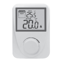
Display description (see fig. 2)
3. Low battery indicator
4. Current room temperature
5. Heat Mode
6. Set temperature
7. Calibration/hysteresis setting
8. Cooling mode indication
9. Heating mode indication
The backlight comes on while turning the multi-function wheel Fig. 1) and will
turn o aer 10 seconds of inactivity
Description of the back of thermostat (see fig. 3)
10. Terminal contacts
11. Battery compartment
Thermostat´s base description (see fig. 4)
12. Mounting holes
13. Terminal for connecting the device
14. Terminal clamp description
Thermostat relay wiring scheme (see Fig. 5)
Thermostat assembly
Thermostat is assembled with a base with mounting holes (see Fig. 4/12). Use
the included screws and dowels for mounting.
Temperature settings
To set the desired temperature turn the control wheel (see Fig. 1). To confirm
the set temperature, press the control wheel (see Fig. 1) or wait 5 seconds for
automatic storage of the set value.
Setting up the operating mode
● Press and hold the wheel (see Fig. 1) for 5 seconds, then turn the wheel to
select the desired mode:
HEAT – Heating
COOL – Cooling
OFF - O (Serves as anti-freeze protection. The heating will only start if the
temperature drops below 7°C).
1
EN