Slimdrive SL NT/SL NT-FR
8
Pre-installation
5.4 Fitting the left-hand module bearer
XX
Fit the left-hand module bearer in compliance with the drawing.
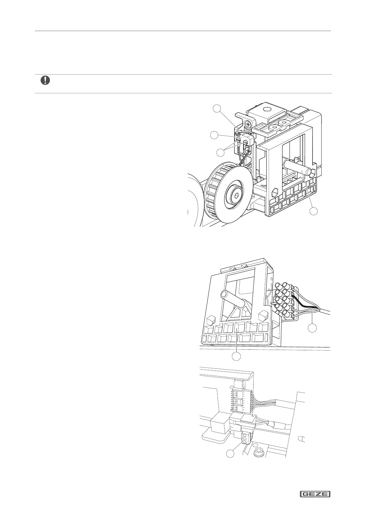
5.5 Connecting the alarm contact to the locking device (optional)
XX
Only screw the red locking pin (1) in again after the cover has been placed on.
XX
Remove screws M2.3 x 10 on the feedback
switch (4) of the locking mechanism.
XX
Place the alarm contact switch (3) on the
feedback switch (4).
XX
Fix both switches in place on the locking
mechanism using M2.3 x 18 (2) screws and
spring washers.
XX
Connect cable.
XX
Shorten the switching ag of the alarm contact
switch.
5.6 Connecting the cable to the left-hand module bearer
XX
Lay cable (2) to the toothed belt locking
(optional) (1), cut to size if necessary, strip and
attach the insulated wire-end ferrules.
XX
Pull the plug (3) for the connection transformer
o the control unit.
XX
Connect the three-core transformer cable to
the plug (3).
Leave the overall length of the transformer cable.
 Loading...