117807-05
GEZE GmbH
Reinhold-Vöster-Strasse 21–29
71229 Leonberg
Germany
Tel.: 0049 7152 203-0
Fax: 0049 7152 203-310
www.geze.com
Symbols and means of representation
Important information and technical notes are emphasised in order to illustrate
the correct operation.
Symbol Meaning
means "important note"
means "additional information"
X
Symbol for an action: Here you have to do something.
X
Observe the sequence if there are several action steps.
Product liability
In accordance with the liability of the manufacturer for their products as dened
in the German “Produkthaftungsgesetz” (Product Liability Act), the information
contained in this brochure (product information and proper use, misuse, product
performance, product maintenance, obligations to provide information and
instructions) is to be observed. Non-compliance releases the manufacturer from
its statutory liability.
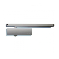
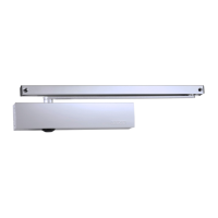
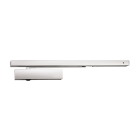
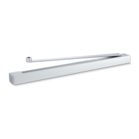
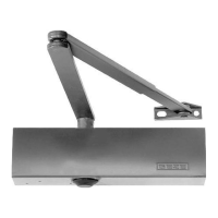
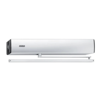
2 TS 3000B
Guide rail with electromechanical hold-open device
2.1 General information
2.1.1 Product description
The guide rail system can electromechanically hold a door leaf in the open
position.
2.1.2 Intended use
The system is designed solely for use in dry rooms.
Any other use than the proper use as well as all changes to the product are
impermissible.
2.1.3 Limitation of liability
GEZE does not accept any liability for direct or indirect damage resulting from
the non-observance of the specications in these instructions of this product.
Technical modications that serve the improvement or further development
of the product can be introduced at any time without any particular
announcement.
GEZE shall not be liable for injuries or damage resulting from unauthorised
modication of the system.
GEZE is not liable if products from other manufacturers are used with GEZE
equipment. Only original GEZE parts may be used for repair and maintenance
work as well.
Please do not hesitate to contact the GEZE customer service for further
information.
2.1.4 Important information
The installation drawing, mounting instructions, maintenance and operating
regulations have to be observed.
The specied range of application has to be observed.
The prescribed mounting dimensions have to be observed.
The prescribed means of fastening have to be used.
All the screws have to be tightened as shown in the drawings.
After mounting and before commissioning:
X
Check the function.
X
Tighten all the clamping screws again.
X
Ensure free accessibility of the ttings for maintenance in accordance with
DIN18357.
X
Make sure that an acceptance test is carried out by qualied and authorised
personnel according to the applicable regulations.
X
In case of re or smoke protection doors, mount an acceptance test plate after
the successful acceptance test.
2.2 Safety instructions
X
The prescribed mounting, maintenance and repair work must be performed
by properly trained personnel authorised by GEZE (see "GEZE user
information for door closer").
X
The country-specic laws and regulations must be observed during safety-
related tests.
X
In accordance with Machinery Directive 2006/42/EC, a risk analysis must
be carried out and the system must be identied in accordance with CE
Identication Directive 93/68/EEC before commissioning.
X
Observe the latest versions of guidelines, standards and country-specic
regulations, in particular:
à BGR 232 “Guidelines for power-operated windows, doors and gates”
à DIN 18650 “Building hardware - Powered pedestrian doors”
à Accident-prevention regulations, in particular BGV A1 “General regulations”
2.2.1 Safety-conscious working
X
Observe the safety instructions for electrical systems and in the wiring
diagram.
X
Protect the workplace against unauthorised entry.
X
Take care to allow sucient space for the movement of components in the
system.
à Risk of injury when a drive is opened through sharp edges and moving parts
(drawing in of hair, clothing, …).
à Risk of injury by crushing, impact, shearing or drawing-in spots.
2.3 Technical data
Operating voltage 24 V DC ±15%
Current consumption 100 mA
Max. ripple permitted 30%
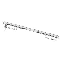
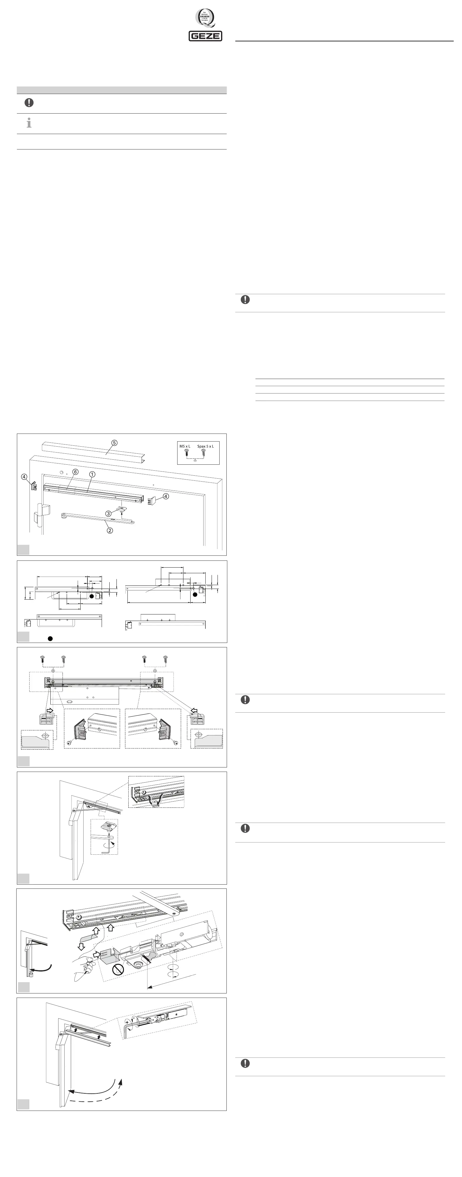
2.4 Description
Designations in g. 9:
1 Guide rail
2 Sliding lever
3 Sliding block
4 End cap
5 Cover panel
6 Electromechanical hold-open device
2.5 Mounting the TS 3000B
2.5.1 Drilling pattern (g. 10)
TS 3000B with E guide rail for direct xing.
X
Mark and drill the xing holes for door closer and guide rail using the tting
template and cut the M5 thread if necessary.
X
Drill additional bore holes with Ø15 mm for cable entry as shown in g. 10.
2.5.2 Mounting the guide rail and end caps (g. 11)
X
Make sure that the cable connection faces to the side of the door leaf.
X
Align spacers (1) at the guide rail.
X
Fasten the mounting screws (2) of the guide rail with 2 Nm.
X
Align and screw on the end caps (3).
X
Fasten the door closer.
2.5.3 Connecting the 24 V power supply (g. 12)
à Red = + (terminal 1)
à White = – (terminal 2)
X
Connect the 24 V cable to the luster terminal (1).
X
Connect the sliding lever (2) to the sliding block (tightening torque 5 Nm).
2.5.4 Adjusting the electromechanical hold-open device (g. 13)
X
Open door leaf (1) to desired open position and x it there.
X
Remove cable protection foil from guide rail (2).
X
Loosen clamping screws (3) of electromechanical hold-open device.
X
Move electromechanical hold-open device until catch contacts sliding block.
X
Securely fasten electromechanical hold-open device with screws (5).
X
To prevent loops, tighten cable and fasten cable protection at
electromechanical hold-open device end (6).
X
Place cable in cable protection and in upper cable chamber behind
electromechanical hold-open device (7).
X
Secure cable with cable protection foil (8).
2.5.5 Functional test of electromechanical hold-open device (g. 14)
X
Open door leaf (1) and engage it in the electromechanical hold-open device.
X
Set the manual release force (2).
Release force for door according to EN 1155:
à 40…120 Nm in an open position of 90°
X
De-energise the electromechanical hold-open device.
The door leaf closes (3).
X
Clip cover on (4).
9
A
ø15 mm Power supply (24 V DC)
RIGHT
LEFT
89
104
15499
154
M5
55
90
10
31.3
428.5
A
26
5 ±1
10
31.3
428.5
OPP HINGE RIGHT
104
154
99
154
M5
OPP HINGE LEFT
A
26
5 ±1
10
M5 x L
Spax 5 x L
M5 x L
Spax 5 x L
a
M4x8 M4x8
a
ss
d d
11
SW 3
a
s
12
kg
a
s
d
f
g
h
j
k
13
+
-
SW 5
a
s
d
f
14
 Loading...