EasyManua.ls Logo

GF Signet 2537 User Manual

GF Signet 2537
16 pages
To Next Page IconTo Next Page
Page #1 background imageLoading...
Page #1 background image
SAFETY INSTRUCTIONS
1. Depressurize and vent system prior to installation or removal.
2. Con! rm chemical compatibility before use.
3. Do not exceed maximum temperature/pressure speci! cations.
4. Wear safety goggles or faceshield during installation/service.
5. Do not alter product construction.
6. If this equipment is used in a manner not speci! ed by the manufacturer, the protection provided
by the equipment may be impaired.
7. This device is not approved for use or installation in hazardous locations.
Signet 2537 Paddlewheel Flowmeter
3-2537.090 Rev G 9/12 English
English
Specifi cations
General
Wetted Materials
Model Suffi x Sensor Body Rotor Pin O-ring
-P0, -P1 glass-! lled PP PVDF, Black;
optional ETFE
w/ or w/o carbon
! ber reinforced
PTFE sleeve
Titanium FPM
-T0 PVDF, Natural PVDF, Natural;
optional ETFE
w/ or w/o carbon
! ber reinforced
PTFE sleeve
PVDF,
Natural
FPM
Case: PBT, yellow
Inside Cover: Valox, black
Wiring Ports: ½ in. NPT threads; liquid-tight
connector accepts cables 7 to
10 mm OD (0.275 in. to 0.394 in.)
Power Requirements
Multi:
with Dry-Contact Relay: 24 VDC nominal, ±10%, regulated
30 mA max. current
with Solid-State Relay: 5 to 24 VDC nominal, ±10%, regulated
30 mA max. current
Digital (S
3
L): 5.0 VDC min. to 6.5 VDC max.
30 mA max. current (1.5 mA nominal)
4 to 20 mA: 400 mV max. ripple voltage
30 mA max. current
Reverse Polarity and Short Circuit Protected: Up to 40 V, 1 hour
Over-Voltage Protection: > 40 VDC over 1 hour
Description
The 2537 Paddlewheel Flowmeter Series offer low # ow, low power and high resolution with various output options such as a Volumetric
Pulse, Pulse Divider, Flow Switch, Digital (S
3
L), or 4 to 20 mA. This unit can be con! gured on-site directly through the built-in user
interface.
The 4 to 20 mA model provides a blind current loop output.
The Digital (S
3
L) model provides a Digital (S
3
L) output for use with the Signet 8900 Multi-Parameter Controller or 9900 Transmitter.
The Multi model uses a single relay (mechanical or solid state) and has three selectable operating modes:
Divider Mode scales the paddlewheel frequency down to accommodate low frequency input devices.
Total Mode outputs one pulse per a set volume of # uid.
Flow Switch Mode uses a single relay for Hi or Lo alarm operation.
A small LCD enables the 2537 to be programmed without any external equipment. During normal operation the display is not visible.
For earlier versions of this sensor, please visit our manual archives at www.gfsignet.com and download the 2537 rev C manual.
Paddlewheel Sensor Performance Specifi cations
Pipe Size Range: DN15 to DN200 (½ in. to 8 in.)
Min. Reynolds Number: 4500
Paddlewheel Frequency: 49 Hz per m/s nominal
(15 Hz per ft/s nominal)
Operating Range: 0.1 m/s to 6 m/s (0.3 ft/s to 20 ft/s)
Linearity: ±1% of max. range @ 25 °C (77 °F)
Repeatability: ±0.5% of max. range @ 25 °C (77 °F)
Electronics Performance Specifi cations
Input Frequency Range: 1 to 1000 Hz
System Response: 100 ms update rate nominal
Environmental Requirements
Enclosure Rating: NEMA 4X/IP65
Storage Temperature: -10 to 75 °C (14 to 167 °F)
Ambient Temperature: 0 to 65 °C (32 to 150 °F)
Relative Humidity: 0 to 90% RH, non-condensing
Altitude: 2000 m (6,562 ft)
Pollution Degree: 2
Output Specifi cations
Signal Averaging: Programmable 0 to 100 seconds
Sensitivity Response: Programmable 0 to 9 scale
Pulse Divider/Total Pulse Output
Pulse Divider Setting: 1.0000 to 99999
Maximum pulse rate: 300 Hz
Maximum pulse width: 50 ms
*3-2537.090*
Question and Answer IconNeed help?

Do you have a question about the GF Signet 2537 and is the answer not in the manual?

GF Signet 2537 Specifications

General IconGeneral
Device TypeFlow Sensor
Accuracy±1% of reading
Enclosure RatingIP65
MaterialPVDF
Size1/2" to 4"
Max. Temperature100°C (212°F)
Measurement Range0.3 to 10 m/s (1 to 33 ft/s)
Resolution0.01 m/s (0.03 ft/s)
Operating Humidity0 to 95% RH (non-condensing)
Output4 to 20 mA, Frequency, Digital (S3L)

Summary

Safety, Description, and Specifications

Safety Instructions

Essential safety guidelines for installation, operation, and maintenance.

Product Description

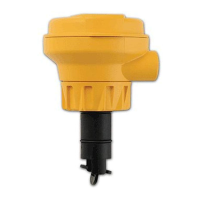
Overview of the flowmeter's capabilities and output options.

Key Performance Specifications

Critical metrics like flow range, linearity, repeatability, and environmental limits.

Output and Power Specifications

Details on signal outputs, power requirements, and electrical performance.

Fluid and Chemical Compatibility

Pressure/Temperature Ratings

Maximum pressure and temperature limits for different body materials.

Chemical Compatibility

Information on material compatibility with various chemicals.

Installation Location and Fittings

Location of Fitting

Recommended sensor placement and upstream/downstream requirements.

Sensor Mounting Position

Guidelines for mounting the sensor in horizontal and vertical pipes.

Installation Procedures

Plastic Sensor Installation Tips

Tips for installing the plastic sensor body and ensuring a proper seal.

Wiring Overview

General guidance on electrical connections for the flowmeter.

Digital (S3L) Output Wiring

Specific wiring instructions for the Digital (S3L) output.

Output Wiring Configurations

4 to 20 mA Output Wiring

Wiring details for the 4 to 20 mA current output signal.

Flow Switch Output Wiring

Wiring details for the Flow Switch output (On-OFF).

Pulse Output Wiring

Wiring details for the Pulse Output (Multi mode).

Relay Wiring (Dry Contact/Solid State)

Wiring for Dry Contact and Solid State relays in On-OFF/Pulse modes.

Operation and Menus

Programming Menus

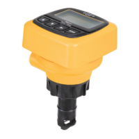
Overview of the programming menus for different flowmeter models.

View Mode Function

How to use the view mode to display flow rate and other information.

Menu Function Details

Flow Unit Setting

Setting volumetric units for flow measurement (e.g., Liters/Gallons per time unit).

K-Factor Configuration

Setting the number of pulses per engineering unit for calibration.

4-20 mA Span Settings

Configuring the 4 to 20 mA output signal span.

Display Contrast Adjustment

Adjusting the visibility of the liquid crystal display.

Flow Unit and K-Factor Configuration

Flow Units Selection

Selecting volumetric units for flow measurement (Liters/Gallons per time unit).

K-Factor Setting

Setting the K-Factor for pulse generation based on fluid volume.

Averaging and Sensitivity Settings

Set Averaging

Configuring the averaging time to smooth erratic flow readings.

Set Sensitivity

Adjusting sensitivity to quickly respond to flow rate changes.

Mode and P-Factor Settings

Mode Selection (Divider/Total)

Choosing between PULSE DIVIDER or PULSE TOTAL output modes.

P-Factor Configuration

Setting the P-Factor for scaling pulse output in Divider or Total modes.

Relay Operation Configuration

Relay Alarm Logic (Hi/Lo)

Selecting HIGH or LOW alarm logic for the relay.

Set Relay Setpoint

Programming the flow rate setpoint for relay activation.

Set Relay Hysteresis

Defining the hysteresis band to prevent relay chattering.

Set Relay Delay

Programming a time delay before relay activation.

K-Factors for Pipe Fittings

Molded Tees K-Factors

K-Factors for molded tees in various pipe materials and sizes.

Saddle Fittings K-Factors

K-Factors for saddle fittings in various pipe materials and sizes.

Metal Tees K-Factors

K-Factors for metal tees (steel, bronze) in various pipe materials and sizes.

K-Factors for Additional Fittings

Union Tees K-Factors

K-Factors for union tees in polypropylene and PVDF.

Weldolets and Brazolets K-Factors

K-Factors for weldolets and brazolets in various materials.

Iron Saddles K-Factors

K-Factors for iron saddles on steel pipe.

Maintenance and Cleaning

Rotor Replacement Procedure

Step-by-step guide for replacing the flowmeter rotor.

Ordering Information

2537 Systems (0.5-4 in. Polypropylene)

Part numbers for 0.5-4 inch systems with polypropylene body.

2537 Systems (5-8 in. Polypropylene)

Part numbers for 5-8 inch systems with polypropylene body.

2537 Systems (0.5-4 in. PVDF)

Part numbers for 0.5-4 inch systems with PVDF body.

Accessories and Replacement Parts

Part numbers for replacement parts and accessories.

Related product manuals